Communication system
a communication system and communication technology, applied in the field of communication systems, can solve problems such as collision risks in the rach, and achieve the effect of satisfying communication quality
- Summary
- Abstract
- Description
- Claims
- Application Information
AI Technical Summary
Benefits of technology
Problems solved by technology
Method used
Image

Examples
first embodiment
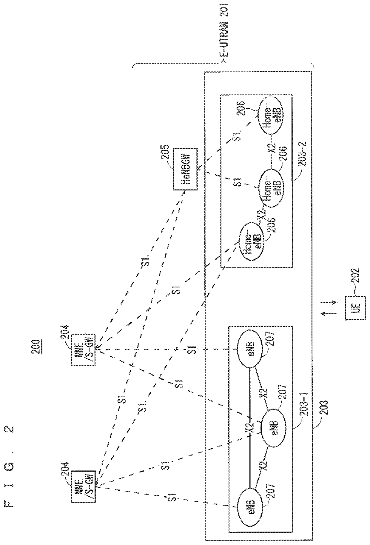
[0091]FIG. 2 is a block diagram showing an overall configuration of an LTE communication system 200 which is under discussion of 3GPP. FIG. 2 is described. A radio access network is referred to as an evolved universal terrestrial radio access network (E-UTRAN) 201. A user equipment device (hereinafter, referred to as a “user equipment (UE)”) 202 that is a communication terminal device is capable of radio communication with a base station device (hereinafter, referred to as a “base station (E-UTRAN Node B: eNB)”) 203 and transmits and receives signals through radio communication.
[0092]Here, the “communication terminal device” covers not only a user equipment device such as a movable mobile phone terminal device, but also an immovable device such as a sensor. In the following description, the “communication terminal device” may be simply referred to as a “communication terminal”.
[0093]The E-UTRAN is composed of one or a plurality of base stations 203, provided that a control protocol ...
second embodiment
[0167]For example, the second embodiment involves a technology to maintain a communication by changing basic beams depending on a change in a communication state, and further involves specifying beams of the user equipment.
[0168]When beamforming is performed in two stages by both of the base station and the user equipment similar to the first embodiment, if the base station cannot specify beams of the user equipment, throughput is affected. Specifically, the base station receives known sequence data form the user equipment, acquires a channel estimation value from the received data, and determines beams to be formed based on the channel estimation value. However, when the base station cannot specify the beams of the user equipment, there is a problem that the base station cannot determine what sort of beams should be formed to enable improvement in throughput.
[0169]For example, when two beams have a high correlation and thus the two beams are hardly separated, it is efficient to tra...
third embodiment
[0215]For example, the third embodiment concerns a countermeasure against interference with another base station.
[0216]The first and second embodiments mainly describe beamforming of uplink (the user equipment→the base station). The third embodiment describes beamforming of the user equipment to improve throughput of downlink (the base station→the user equipment).
[0217]It is known that a method in which the base station acquires downlink channel information from a received uplink signal by using reciprocity, and calculates a precoding weight based on the acquired downlink channel information, and multiplies downlink transmission data by the calculated precoding weight is effective to enhance throughput. However, data transmitted in such a way does not consider an interference component from another base station, and thus there is a problem that cannot gain an expected throughput.
[0218]Solutions to this problem is described below.
[0219]The first method is a method in which interferen...
PUM
 Abstract
Description
Claims
Application Information
 - R&D
- Intellectual Property
- Life Sciences
- Materials
- Tech Scout
- Unparalleled Data Quality
- Higher Quality Content
- 60% Fewer Hallucinations
Browse by: Latest US Patents, China's latest patents, Technical Efficacy Thesaurus, Application Domain, Technology Topic, Popular Technical Reports.
© 2025 PatSnap. All rights reserved.Legal|Privacy policy|Modern Slavery Act Transparency Statement|Sitemap|About US| Contact US: help@patsnap.com