
Diffuser for separator vessel

a separator vessel and diffuser technology, applied in the direction of auxillary pretreatment, separation process, furnace, etc., can solve the problems of affecting the flow rate of the separator vessel, so as to achieve the effect of improving the flow rate distribution

Active Publication Date: 2008-01-08
UOP LLC
View PDF9 Cites 28 Cited by
  • Summary
  • Abstract
  • Description
  • Claims
  • Application Information

AI Technical Summary

Benefits of technology

[0010]A diffuser is provided for a TSS vessel designed to separate particulate solids from a contaminated gas stream entering the vessel through an inlet or inlet pipe. The diffuser improves flow distribution of the contaminated inlet stream from the inlet pipe among the plurality of separation cyclones mounted in the vessel a distance below the inlet. A process utilizing such a diffuser is also provided.
[0017]Accordingly, an object of the present invention is to provide a diffuser for a TSS vessel wherein the diffuser is configured to be mounted at an inlet to the TSS and is operable to promote proper flow distribution.
[0018]An advantage of the diffuser is that it disperses flow in a controlled fashion within the vessel interior, yielding a conical flow profile with improved uniformity.
[0019]Another advantage is improving operational efficiency of the vessel by optimizing the usage of the plurality of cyclones.

Problems solved by technology

For every ton of cracked product made, approximately 5 tons of catalyst are needed, hence the considerable circulation requirements.
Coupled with this need for a large inventory and recycle of catalyst with small particle diameters is the ongoing challenge to prevent this catalyst from exiting the reactor or regenerator in effluent streams.
Catalyst particles are abrasive and thus are capable of damaging and eroding components located downstream of the reactor, such as a turbine.
If exposed to catalyst particles, blades of the turbine would erode and result in loss of power recovery efficiency.
Moreover, small catalyst fines do not erode expander turbine blades significantly but can accumulate on the blades and casing to cause rubbing.
While normally sized catalyst particles are effectively removed in the internal regenerator cyclones, fines material (generally catalyst fragments smaller than about 50 microns resulting from attrition and erosion in the harsh, abrasive reactor / regenerator environment) is substantially more difficult to separate.
This solids level can present difficulties related to the applicable legal emissions standards and are still high enough to risk damage to the power recovery expander turbine.
If undiffused, gas flow from the inlet pipe travels downwardly toward the cyclones, the stream concentrating on some of the cyclones, while other cyclones not within the direct path of the stream are not used with optimal efficiency.

Method used


Image

  • Diffuser for separator vessel
  • Diffuser for separator vessel
  • Diffuser for separator vessel

Examples


Embodiment Construction

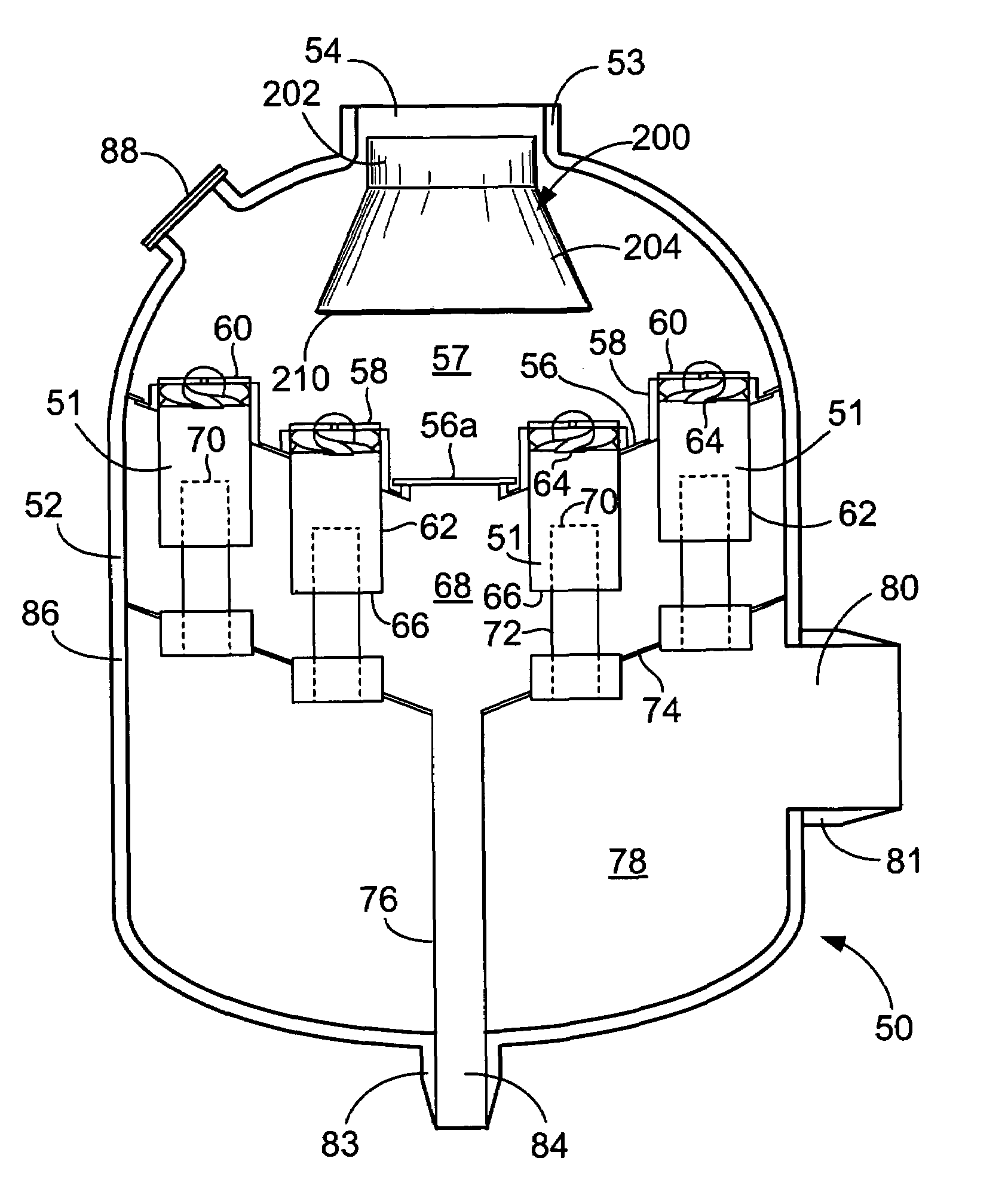
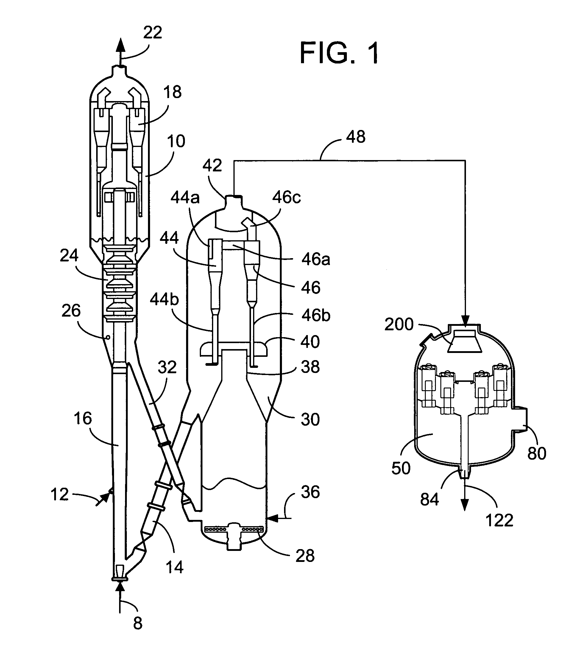
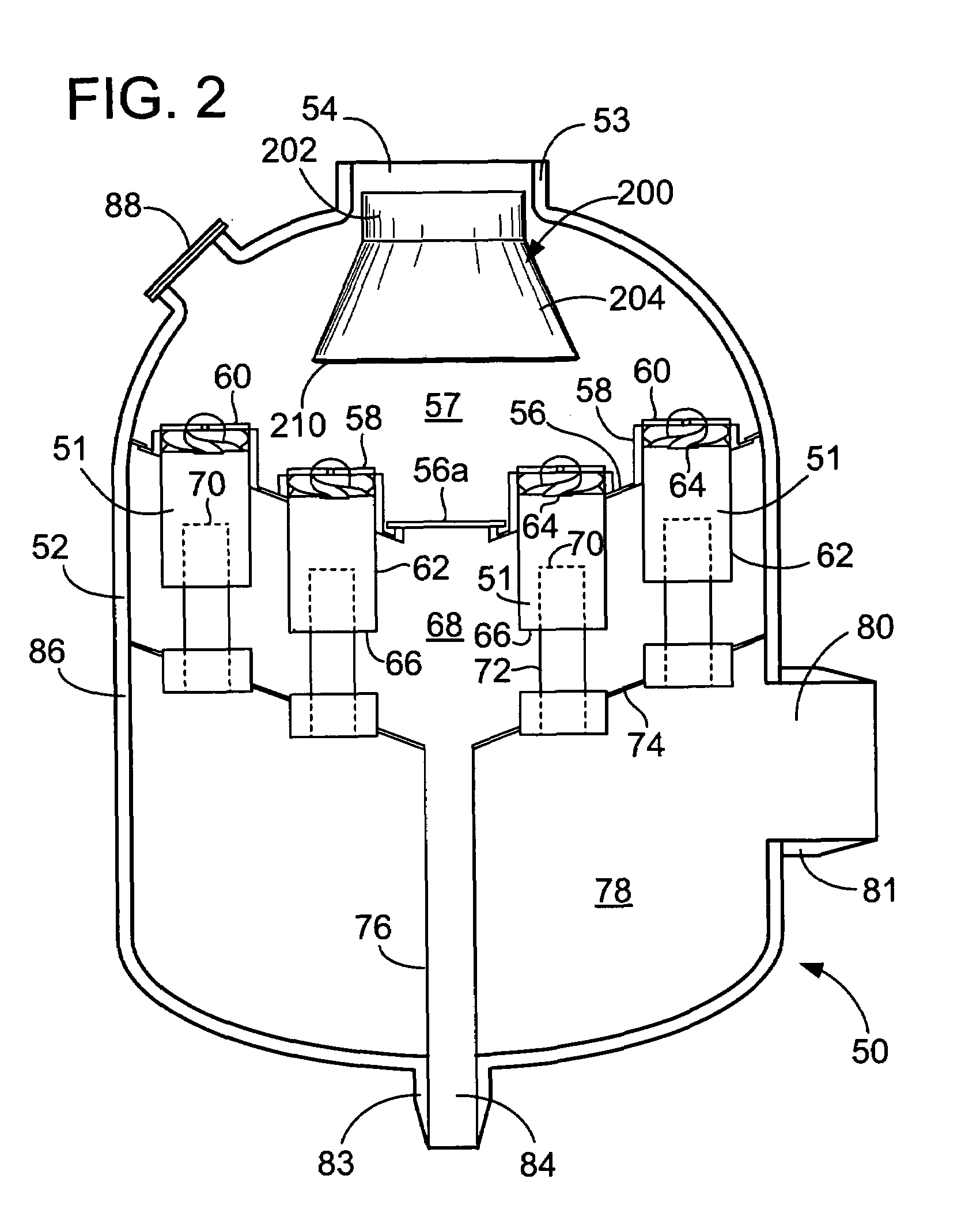
[0028]The present invention applies to the purification of a broad range of solid-contaminated gas streams, and especially those containing dust particles in the 1 to 20 μm range. A number of commercial gas purification operations meet this description, including the treatment of effluent streams of solid catalyst fluidized bed processes, coal fired heaters, and power plants. Several well-known refinery operations rely on fluidized bed technology, such as a preferred embodiment of the process for converting methanol to olefins (MTO), as described in U.S. Pat. No. 6,137,022, using a solid catalyst composition. Another area of particular interest lies in the purification of FCC effluent streams that contain entrained catalyst particles resulting from attrition, erosion, and / or abrasion under process conditions within the reactor. As mentioned, fluid catalytic cracking (FCC) is a well-known oil refinery operation relied upon in most cases for gasoline production. Process variables typi...


PUM

PropertyMeasurementUnit
Angleaaaaaaaaaa
Fractionaaaaaaaaaa
Fractionaaaaaaaaaa

Abstract

A third stage separator vessel includes a diffuser to promote uniform flow among an array of separation cyclones in the vessel. The vessel has an inlet to receive a gas stream containing solid particles, and the diffuser is mounted at the inlet so that at least some of the stream passes through the diffuser. In an embodiment, a gap between the diffuser and the inlet causes some of the gas stream to flow over an outer surface of the diffuser. The diffuser preferably includes a perforated plate mounted across a wide end of a frustoconical portion. The plate has a plurality of openings through which the flow passes. The openings in the plate have various sizes and positions to direct a greater amount of flow through radially outward portions of the plate than from a central portion of the plate.

Description

FIELD OF THE INVENTION[0001]The present invention generally relates to a diffuser for a separator vessel that removes particles from a gas stream laden with solids and more particularly relates to a third stage separator (TSS) vessel for removing catalyst fines from exhaust gas of a fluid catalytic cracking (FCC) unit.BACKGROUND OF THE INVENTION[0002]FCC technology has long been a predominant means of producing gasoline. In an FCC process, gasoline is formed as the result of cracking heavier (i.e. higher molecular weight), less valuable hydrocarbon feed stocks such as gas oil. Although FCC is a large and complex process involving many factors, a general outline of the technology is presented here in the context of its relation to the present invention.[0003]The FCC process generally includes a reactor that is closely coupled with a regenerator, followed by downstream hydrocarbon product separation. Hydrocarbon feed contacts catalyst in the reactor to crack the hydrocarbons down to s...

Claims


Application Information

Patent Timeline
IPC IPC(8): B01D45/12
CPCB01D45/12
Inventor HEDRICK, BRIAN W.JOHNSON, II, RICHARD A.SECHRIST, PAUL A.IDDIR, HADJIRA
Owner UOP LLC
Learn More