Air supply apparatus for a fuel cell

a fuel cell and air supply technology, applied in the direction of fuel cells, electrical devices, cell components, etc., can solve the problems of increasing the size and weight of the fuel cell unit on which the fans are mounted, the pressure (flow rate) of the sucked air is not uniform, and the electric consumption increases. , to achieve the effect of increasing the size and weigh

Inactive Publication Date: 2008-01-01
HONDA MOTOR CO LTD
View PDF6 Cites 14 Cited by
  • Summary
  • Abstract
  • Description
  • Claims
  • Application Information

AI Technical Summary

Benefits of technology

[0005]As described above, the prior art has had drawbacks in that since two fans are used, one for supplying reaction air and one for supplying cooling air, electricity consumption increases and the fuel cell unit on which the fans are mounted increases in both size and weight.
[0008]Therefore, an object of this invention is to solve the problems described above and to provide an air supply apparatus for a fuel cell that reduces the consumed electricity necessary to drive a fan for supplying cooling air or reaction air to the fuel cell, and that suppresses an increase in size and weight of the fuel cell unit.
[0009]A second object of this invention is to solve the problems described above and to provide an air supply apparatus for a fuel cell in which air is uniformly fed to each unit cell constituting the fuel cell while a centrifugal fan is used that does not compress sucked air to a high pressure, thereby allowing the fuel cell to be operated stably and efficiently, and the consumed electricity necessary to drive the air supply apparatus to be reduced.
[0011]According to a second aspect of this invention, there is provided an air supply apparatus of a fuel cell that changes chemical energy of a fuel supplied through a fuel electrode and oxidant supplied through an air electrode to electric energy, comprising: an air blower sucking in air to supply to the air electrode of the fuel cell; a manifold disposed between the air blower and the fuel cell and having a passage through which the sucked air is supplied to the air electrode of the fuel cell; and a flow-uniforming device disposed in the passage of the manifold such that flow rate of the sucked air to be supplied to the air electrode of the fuel cell is made uniform.

Problems solved by technology

As described above, the prior art has had drawbacks in that since two fans are used, one for supplying reaction air and one for supplying cooling air, electricity consumption increases and the fuel cell unit on which the fans are mounted increases in both size and weight.
However, using a centrifugal fan or other device that does not compress sucked or aspirated air at high pressure as the air supply apparatus has drawbacks in that the pressure (flow rate) of the sucked air is not uniform and the cooling air and reaction air cannot be supplied uniformly to each unit cell because the back pressure of the sucked air does not reach a high pressure.
However, this approach has had drawbacks in that a large amount of electricity must be consumed to drive the pump or other device capable of compressing cooling air or reaction air to a high pressure.

Method used


Image

  • Air supply apparatus for a fuel cell
  • Air supply apparatus for a fuel cell
  • Air supply apparatus for a fuel cell

Examples


first embodiment

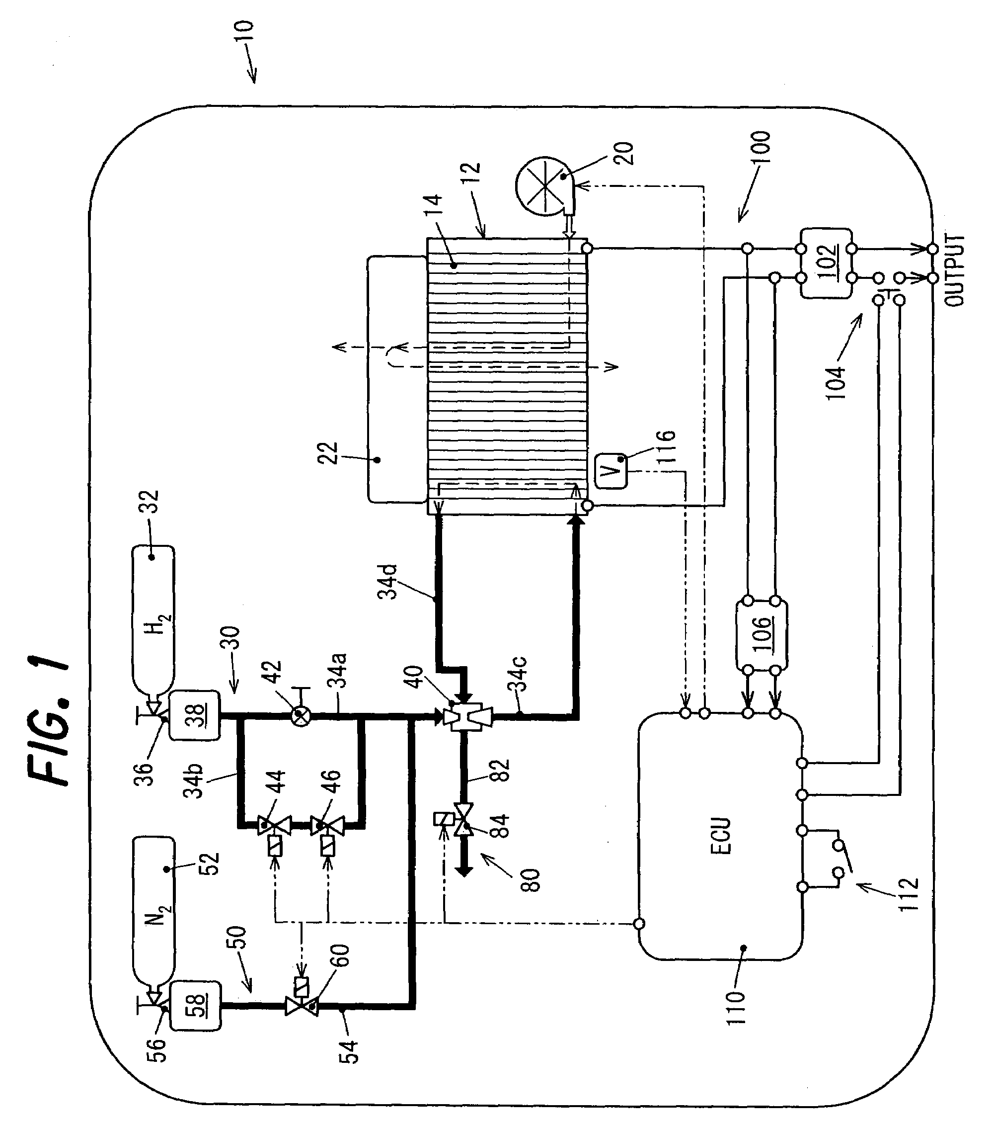
[0027]FIG. 1 is a schematic view showing an air supply apparatus for a fuel cell according to this invention as part of a fuel cell unit.

[0028]In FIG. 1, the symbol 10 indicates a power generating unit including the air supply apparatus for a fuel cell according to the first embodiment. The power generating unit 10 is packaged into a portable size with a fuel cell 12, pipes, and other such elements necessary for power generation.

[0029]The fuel cell (specifically, a stacked member, or cell stack) 12 is formed by stacking a plurality of unit cells (cells) 14. Specifically, 70 cells can be stacked in this manner. The fuel cell generates a rated output of 1.05 kW. The unit cells 14 are conventionally known solid polymer fuel cells including an electrolyte membrane (solid polymer membrane), an air electrode (cathode electrode) and fuel electrode (anode electrode) on both sides of the membrane, and a separator disposed on the outer sides of both electrodes. A detailed description thereof ...

second embodiment

[0068]Next, the air supply apparatus for a fuel cell according to this invention will be described.

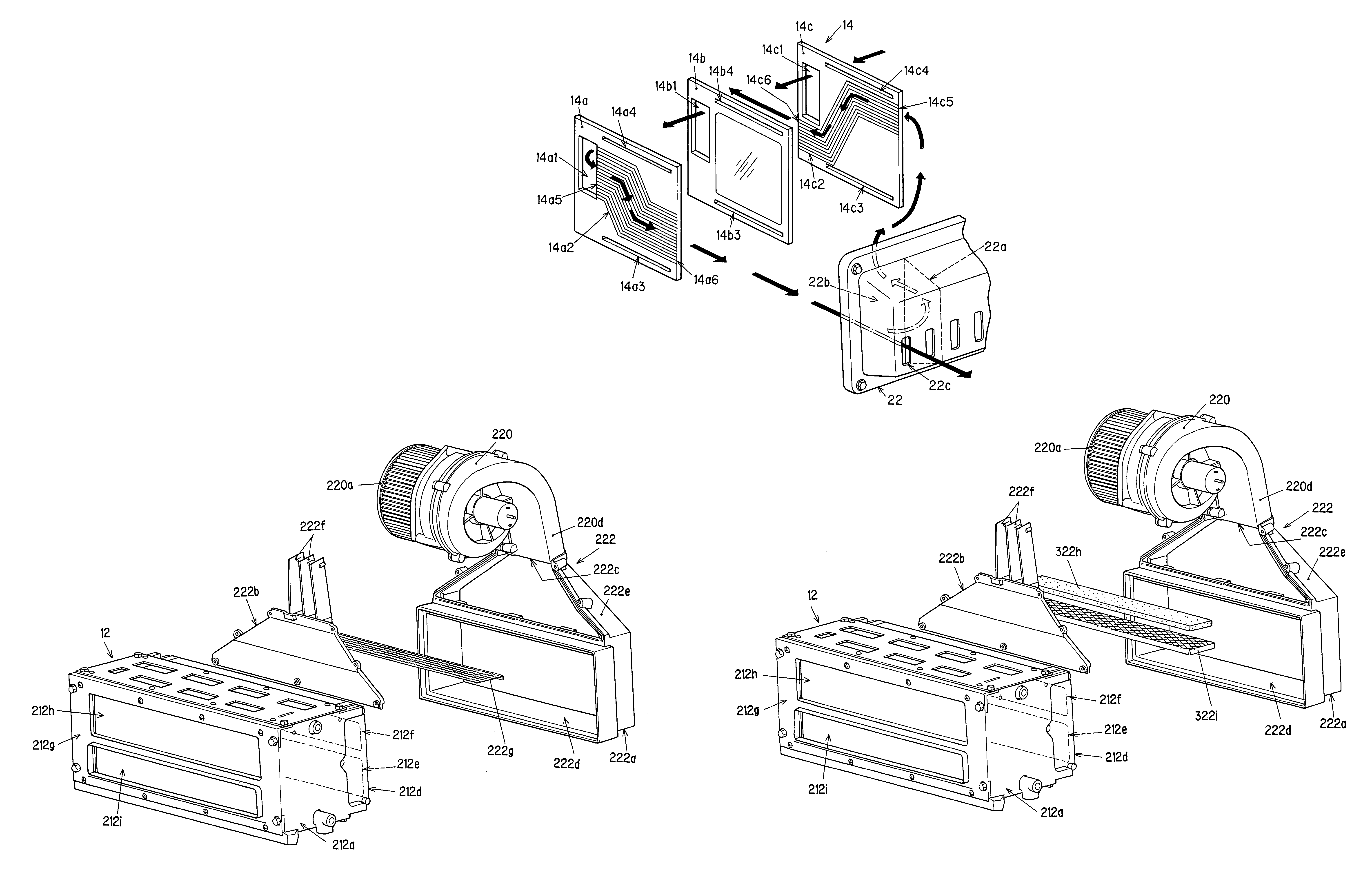
[0069]FIG. 6 is a schematic view showing the air supply apparatus for a fuel cell according to the second embodiment of this invention as part of a fuel cell unit. The difference between this embodiment and the first embodiment is that an air blower 220 for feeding cooling air and reaction air to the fuel cell 12 is connected to the fuel cell 12 via a manifold 222, and the air sucked in by the air blower 220 is fed to the unit cells 14 as cooling air or reaction air via the manifold 222. Also, the cooling air and reaction air passing through the unit cells 14 is expelled out of the fuel cell 12.

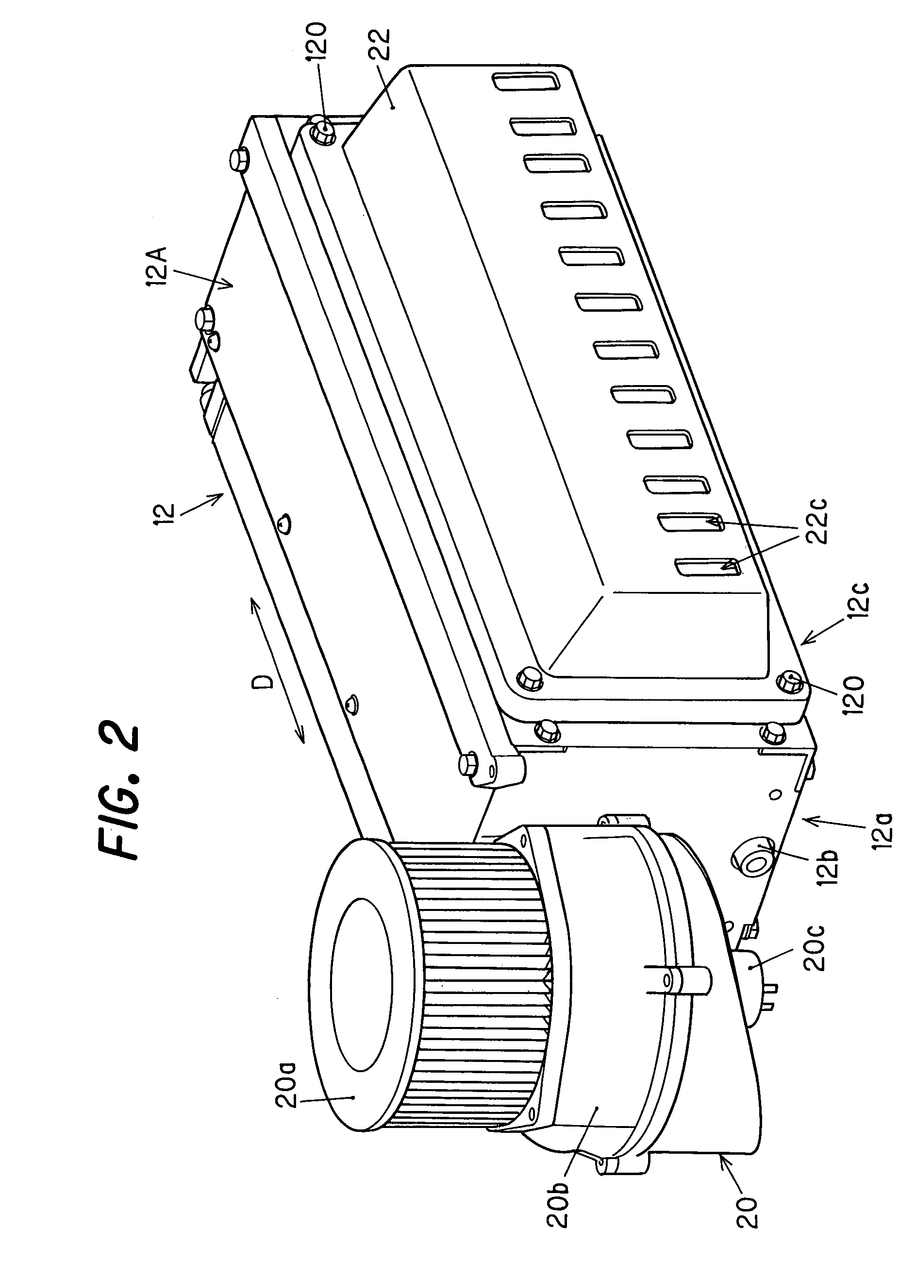
[0070]FIG. 7 is a perspective view of the fuel cell 12, and of the air blower 220 and manifold 222 connected thereto.

[0071]The fuel cell 12 is provided with a case 212A, and the unit cells 14 are disposed in a stacked arrangement inside the case 212A, as shown in FIG. 7. The side surface 212a of...

third embodiment

[0085]Next, the air supply apparatus for a fuel cell according to this invention will be described.

[0086]FIG. 9 is a perspective view showing the air supply apparatus for a fuel cell according to the third embodiment. The main difference with the second embodiment is that in the present embodiment, the configuration is such that a sponge plate is provided as a flow-uniforming device instead of a punching plate.

[0087]In FIG. 9, the symbol 322h indicates a plate of sponge made of urethane (i.e., a sponge configured to be a plate). The sponge plate 322h is disposed downstream of the current plates 222f (between the expanding section 222e and the air discharge vent 222d) via a metallic base plate 322i provided with a plurality of large holes.

[0088]Specifically, in the third embodiment, the air sucked in by the air blower 220 is made more uniform by the current plates 222f to have a substantially uniform current speed, and is then made more uniform and endowed with a uniform current spee...


PUM

PropertyMeasurementUnit
pressureaaaaaaaaaa
pressureaaaaaaaaaa
chemical energyaaaaaaaaaa

Abstract

In an air supply apparatus of a fuel cell having a fuel electrode and an air electrode, the air sucked in by an air blower is fed as cooling air to the cooling are passage groove, and a manifold is provided as a communicating member to communicate the exhaust side of a cooling air passage groove with the suction side of a reaction air passage groove (air electrode) such that both cooling air and reaction air are fed to the fuel cell by driving a single air blower. With this, the consumed electricity needed to drive the air supply fan can be reduced, and an increase in the size and weight can be suppressed. In addition, a flow-uniforming device such as current plates, a punching plate or a sponge plate are provided in the manifold.

Description

BACKGROUND OF THE INVENTION[0001]1. Field of the Invention[0002]The present invention relates to an air supply apparatus for a fuel cell.[0003]2. Description of the Related Art[0004]Fuel cells generate power by an electrochemical reaction caused by hydrogen supplied to a fuel electrode and reaction air (oxygen) supplied to an air electrode, and the reaction air is normally supplied to the air electrode by means of a fan (air blower). Also, fuel cells are supplied with cooling air for suppressing temperature increases due to power generation, and in conventional practice the cooling air is supplied by a fan provided separately from the fan for supplying the reaction air (as taught, for example, in FIG. 1, etc., in Japanese Laid-Open Patent Application No. Hei 7(1995)-6777.SUMMARY OF THE INVENTION[0005]As described above, the prior art has had drawbacks in that since two fans are used, one for supplying reaction air and one for supplying cooling air, electricity consumption increases ...

Claims


Application Information

Patent Timeline
Patent Type & Authority Patents(United States)
IPC IPC(8): H01M2/00H01M8/04
CPCH01M8/04014H01M8/04089H01M8/0258Y02E60/50H01M8/2483H01M8/0267H01M8/2484
Inventor HATSUGAI, TSUTOMUKIURA, TOSHIROU
Owner HONDA MOTOR CO LTD
Why Eureka
Try Eureka