
Phantom powered capacitor microphone and a method of using a vacuum tube in the same

a capacitor microphone and vacuum tube technology, applied in the field of capacitor microphones, can solve the problems of insufficient power supply to the plate of vacuum tubes, large noise generated by switching, and inability to operate vacuum tubes, etc., and achieve the effect of no noise and easy availability in markets

Inactive Publication Date: 2007-11-13
AUDIO-TECHNICA
View PDF4 Cites 9 Cited by
  • Summary
  • Abstract
  • Description
  • Claims
  • Application Information

AI Technical Summary

Benefits of technology

[0013]The subject matter of this invention is that in a phantom powered capacitor microphone of which a vacuum tube is used as an impedance converter, in order to heat the heater of the vacuum tube a heater power supply including a down-converter which generates no noise and which is easily-offered in markets is obtained from the phantom power supply.

Problems solved by technology

Therefore, since a general 48V phantom power supply cannot afford to supply that power, the exclusive power supplies are used.
In this condition, the power supplied to the plate of the vacuum tube is insufficient and the vacuum tube cannot be operated.
However, following problems will occur.
Since in the converter using the pulse width modulation method, the input voltage of the converter is switched on and off, large noise is generated because of the switching.
The noise enters to a supply voltage, and then, the noise increases a microphone noise.
Further, since an inductor is used in the pulse width modulation converter, an external magnetic field is generated by the current with noise flowing in the inductor and the external magnetic field is magnetically coupled with an output transformer of a microphone, whereby the microphone noise is generated.
The other problem is that the down-converter which can convert 10V to 1.25V is rarely-offered in markets, because it's application is limited.

Method used


Image

  • Phantom powered capacitor microphone and a method of using a vacuum tube in the same
  • Phantom powered capacitor microphone and a method of using a vacuum tube in the same

Examples


Embodiment Construction

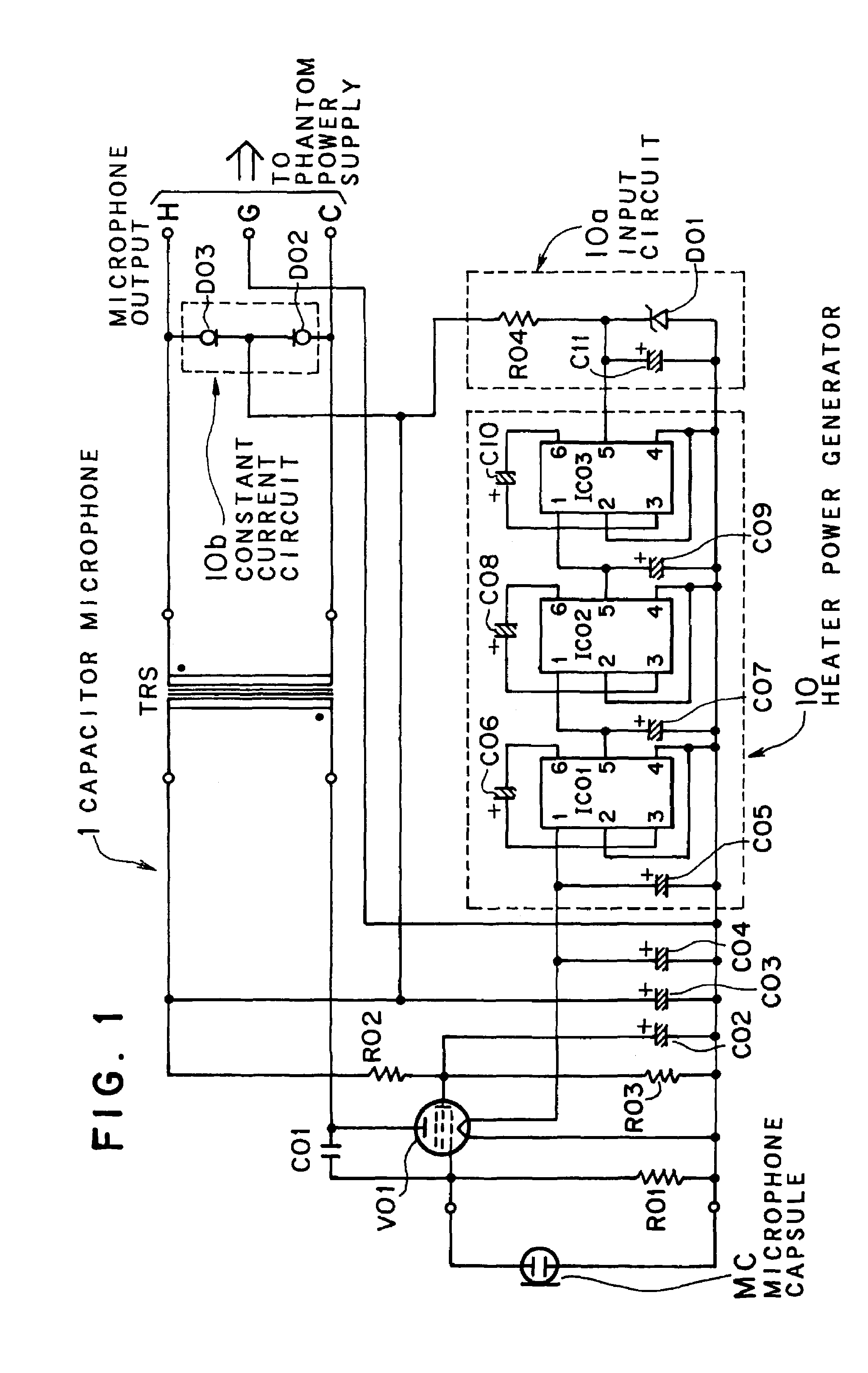
[0021]An embodiment of this invention will be described according to a circuit diagram of a capacitor microphone 1 as shown in FIG. 1. The capacitor microphone of this invention is powered by a phantom power supply (phantom powered capacitor microphone). The phantom power supply (not shown), which is publicly known, includes two 6.8 kΩ resistors seriously connected between the hot side and the cold side of the balance-transmission and a DC 48 V power supply connected between the connecting point of the two resistors and the ground.

[0022]In FIG. 1 MC is a microphone capsule (so called a mike) of the capacitor microphone. The capsule is an electret capacitor type microphone capsule in this embodiment, however the capsule also may be a kind of a capsule which needs a polarization power supply.

[0023]V01 is a vacuum tube which is used as an impedance converter connected to the microphone capsule MC. In this embodiment, type no. 6418 of a directly heated pentode vacuum tube of Raytheon co...


PUM


Abstract

The present invention provides a low noise phantom powered capacitor microphone and a method of using a vacuum tube as an impedance converter of the microphone capsule in the capacitor microphone with no exclusive power supply.In the phantom powered capacitor microphone of which a vacuum tube V01 is used as the impedance converter, a part of the voltage supplied from the phantom power supply is converted to a predetermined voltage by one or more switched capacitor voltage converters, for example, by three switched capacitor voltage converters IC01, IC02 and IC03 seriously connected as three stages to obtain the heater voltage of the vacuum tube V01.

Description

FIELD OF THE INVENTION[0001]The present invention relates to a capacitor microphone powered by a phantom power supply (a phantom powered capacitor microphone) and especially relates to the phantom powered capacitor microphone and a method of using a vacuum tube as an impedance converter of a microphone capsule thereof.BACKGROUND OF THE INVENTION[0002]A FET (Field Effect Transistor) or a vacuum tube is used as an impedance converter of a capacitor microphone, because impedance between a vibrating plate and a fixed electrode placed and faced to each other in a capacitor microphone capsule is remarkably high.[0003]When a vacuum tube is used as an impedance converter of a capacitor microphone, exclusive power supplies generally need to be prepared. A heater power supply for heating a heater and a plate power supply for flowing a plate current are necessary for operating the vacuum tube.[0004]Generally, a vacuum tube which is used as an impedance converter needs a heater power supply of ...

Claims


Application Information

Patent Timeline
Patent Type & Authority Patents(United States)
IPC IPC(8): H04R3/00H04R19/04H03F3/181
CPCH03F3/181H04R19/04H04R3/00
Inventor AKINO, HIROSHIKIOKE, TATSUOOKITA, SHIOTO
Owner AUDIO-TECHNICA
Learn More