
Workstation for computerized analysis in mammography

a workstation and mammogram technology, applied in the field of mammogram workstations, can solve the problems of large work area, large work area, and possibility of misplacement, error or even loss, and achieve the effect of reducing the number of workstations

Active Publication Date: 2007-10-30
SIEMENS COMP AIDED DIAGNOSIS
View PDF14 Cites 0 Cited by
  • Summary
  • Abstract
  • Description
  • Claims
  • Application Information

AI Technical Summary

Benefits of technology

[0016]An additional object of the present invention is to provide a system and method for collating and filing mammogram films and data that can be carried out in smaller work areas. Today collating and filing requires relatively large areas to collate and file the physical records produced by mammogram screening.
[0018]A further objective of the present invention is to provide a method for automatically isolating, that is separating, the digitized images generated from analog film mammograms of one patient from another. Additionally, it is an object of the invention to keep the film mammograms and their associated physical data, e.g. digitized image printouts, of one patient physically separate from those of another. This separation simplifies filing the mammograms in physical storage containers. Both of these separation objectives are achieved with separator films described in the present invention.

Problems solved by technology

The analysis, even after using the above techniques, still remains mainly subjective.
The commingling of film and printed reports allows for the possibility of misplacement, error or even loss.
In addition, the separation of films and printed reports, and then their subsequent collation generally requires a large work area.
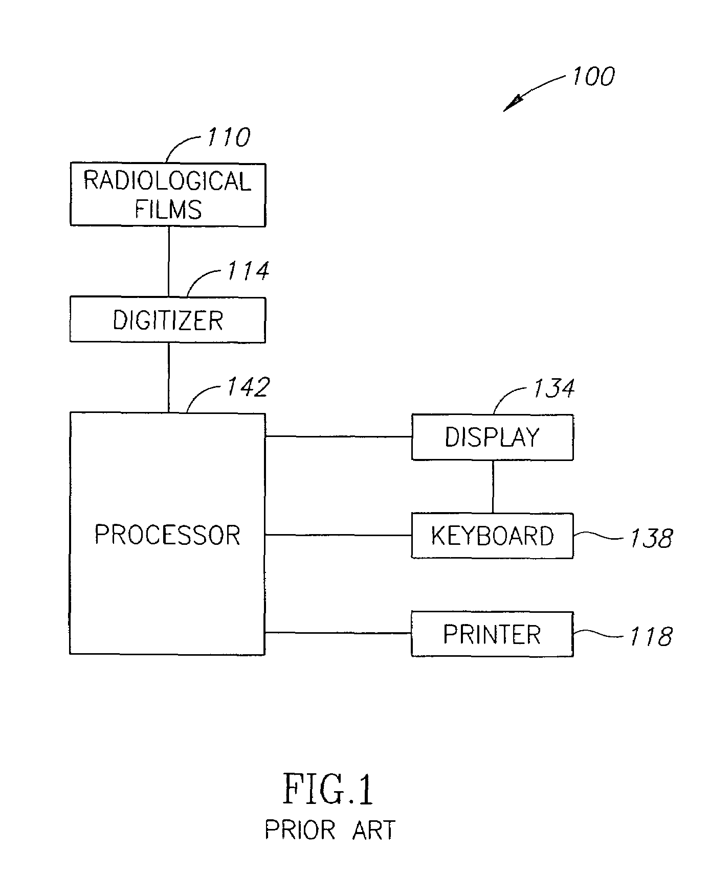
All appear to be computer-based systems and methods dealing with digital records, and they do not provide for collating and filing physical records.
A workstation and method for retaining, organizing and assisting in the filing of radiological film mammograms together with related digitally produced printouts is required but lacking.

Method used


Image

  • Workstation for computerized analysis in mammography
  • Workstation for computerized analysis in mammography
  • Workstation for computerized analysis in mammography

Examples


Embodiment Construction

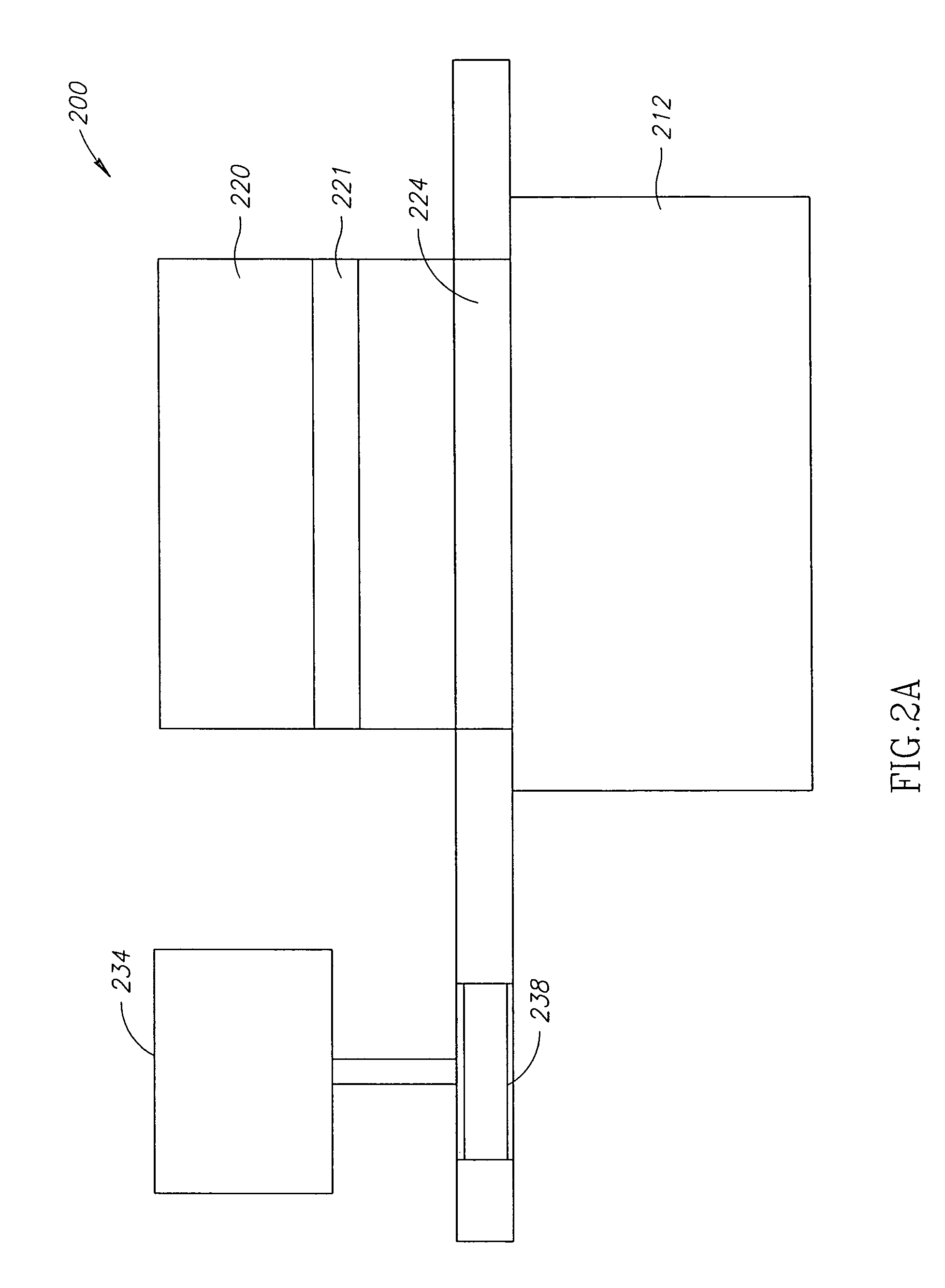
[0041]FIGS. 2A-2C, to which reference is now made, show various schematic views of a workstation of the present invention, generally referenced as 200, constructed according to an embodiment of the present invention. FIG. 2A is a full front view, FIG. 2B is a cut-away front view and FIG. 2C is a side view of the workstation. Workstation 200 includes a display 234, a keyboard 238 and a computer processor 242, the latter located within the body 212 of workstation 200. It also may include an input device (not shown), which may be a computer mouse, touch screen or other such devices.

[0042]Integrated with body 212 of workstation 200 is a scanner 221 which is in electronic communication with processor 242. A film feed 220 of scanner 221 is shown at the top of workstation 200. Radiological films containing mammogram images are placed in film feed 220 and scanned through scanner 221 from which digitized images are transferred to processor 242 and then displayed on display 234. The scanned f...


PUM


Abstract

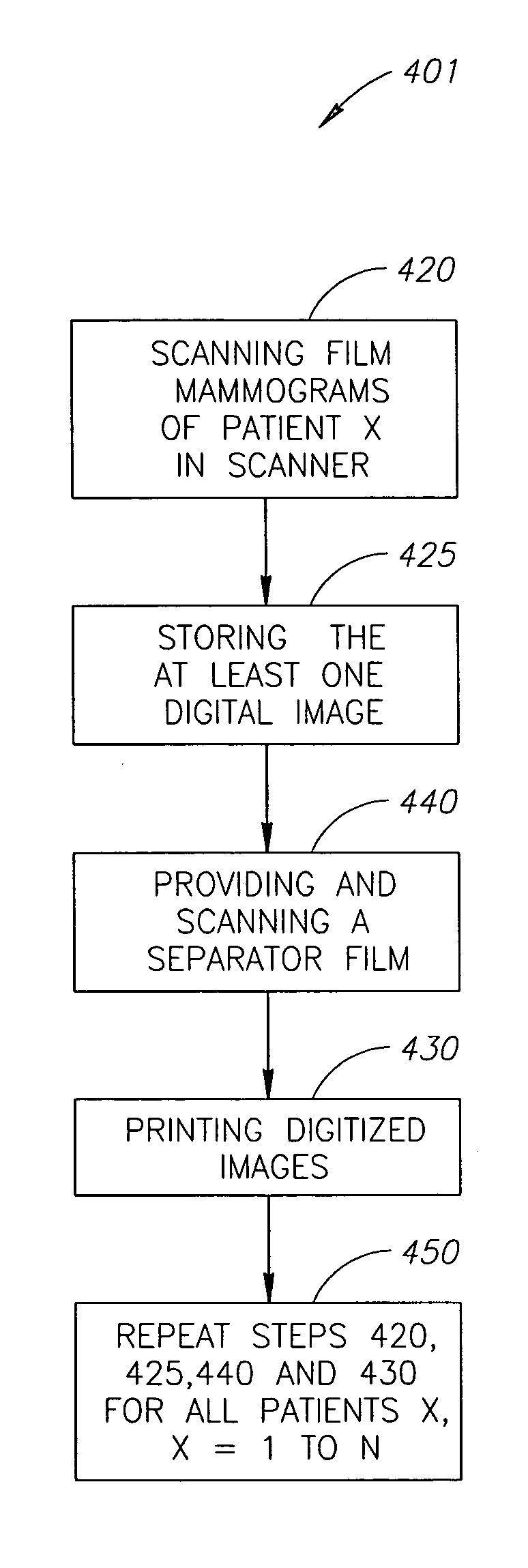
A method of separating and collating mammogram records, the method including the step of providing and scanning a separator film having identifiable features which when scanned identify the film as a separator film, thereby assisting in the separation of mammograms of different patients. A separator film for use with a mammogram workstation the film having at least one identifiable characteristic recognizable by the workstation's processing means so that the film is identified as a separator film separating mammograms of different patients. A workstation system for collating radiological film mammograms which includes a scanner which digitizes radiological film mammograms and scans a separator film carrying identifiable features for identifying the film as a separator film usable to separate mammograms of different patients.

Description

FIELD OF THE INVENTION[0001]The present invention relates to a mammogram workstation and a method for using such a workstation.BACKGROUND OF THE INVENTION[0002]Breast cancer is one of the most common types of cancer afflicting Western society. It is estimated that the spread of the disease has risen in the United States, from one in twenty women being afflicted in 1940, to one in eight in 1995. The American Cancer Society estimated that 183,000 new cases of breast cancer were reported during 1995. In the United States, some 46,000 women die from the disease per year. Today, it is accepted that the best way to detect breast cancer in its early stages is by annual mammography screening of women aged 40 and up.[0003]Today, radiologists generally interpret mammograms visually, using a light box, and their analysis is largely subjective. Film masking is used to highlight additional detail. In many cases, the radiologist employs supplementary tools such as a magnifying glass and bright li...

Claims


Application Information

Patent Timeline
IPC IPC(8): G06K9/00G06T7/00G16H30/20G16H30/40
CPCG06Q50/24G06T7/0012G06T2207/30068G16H30/20G16H30/40
Inventor BAMBERGER, PHILIPPE NATHANLEICHTER, ISAACMERLET, NICOLAS J.
Owner SIEMENS COMP AIDED DIAGNOSIS
Learn More