
Storage virtualization system and method having a virtualization switch

Inactive Publication Date: 2007-10-23
HITACHI LTD
View PDF14 Cites 25 Cited by
  • Summary
  • Abstract
  • Description
  • Claims
  • Application Information

AI Technical Summary

Benefits of technology

[0008]It is therefore an object of the present invention to provide a virtualization system capable of mitigating the load imposed on an apparatus (virtualization apparatus) to perform a virtualization processing between a server and a storage system.
[0009]Another object of the present invention is to provide a virtualization system capable of achieving desired performance in association with increase in the load imposed on the virtualization apparatus executing virtualization processing between a server and a storage system.
[0010]Further another object of the present invention is to provide a virtualization system in which even if the computer managing virtualization fails, input and output operations of data are not adversely influenced between a server and a storage system.
[0015]According to the present invention, there is provided a virtualization system in which the computer to conduct the virtualization does not become a processing bottleneck in the overall system. Moreover, according to the present invention, there is provided a virtualization system which achieves desired performance in association with increase in the processing load in a section executing the virtualization processing.
[0016]According to the present invention, there is provided a virtualization system in which even when a failure occurs in the virtualization apparatus, the failure does not exert adverse influence on any external device.

Problems solved by technology

Recently, the amount of data used in an information processing system has been considerably increased and hence storage management expenses imposed on the user have been increased.
It is therefore not practical to cope with all operating systems.
This leads to a problem that a limit of performance of the computer becomes a limit of performance of the system.
For example, saving data from a storage system to another storage system imposes quite a heavy load on the computer.
If the computer implementing the virtualization fails, the entire storage system cannot be used.

Method used


Image

  • Storage virtualization system and method having a virtualization switch
  • Storage virtualization system and method having a virtualization switch
  • Storage virtualization system and method having a virtualization switch

Examples


Embodiment Construction

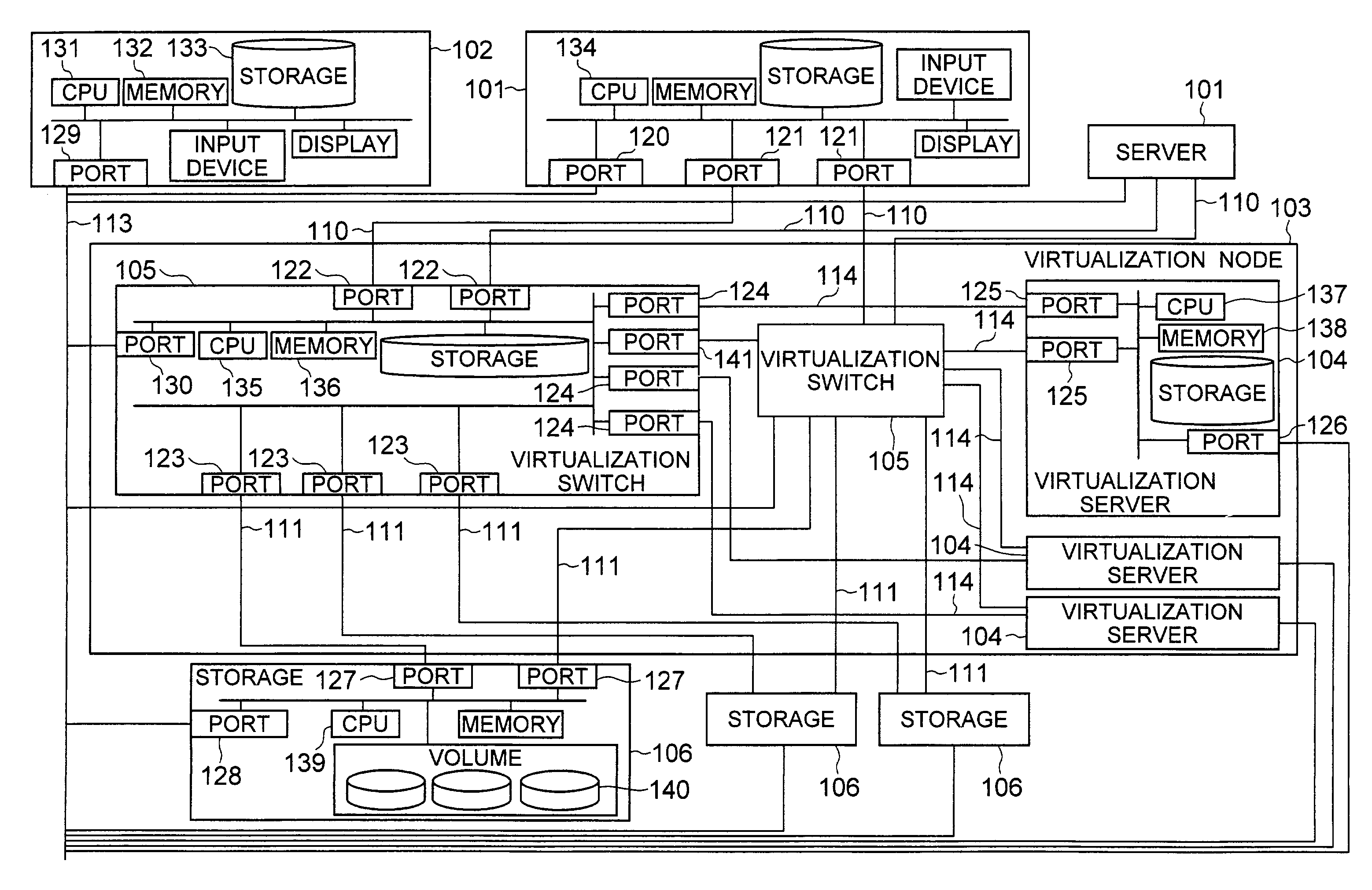
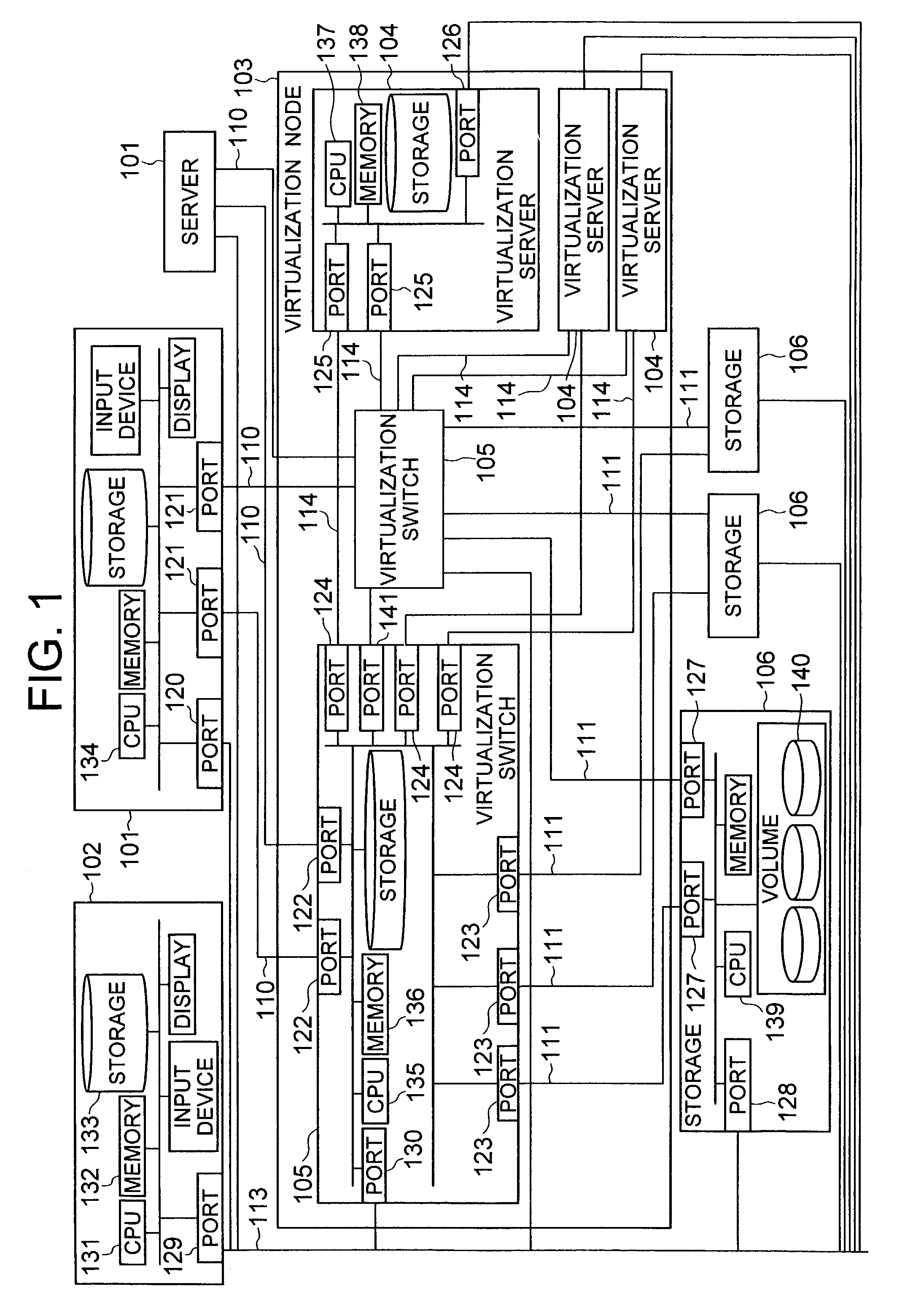
[0034]FIG. 1 shows a configuration of an embodiment of a system according to the present invention. The system includes servers 101, storage systems 106, a virtualization apparatus (virtualization node) 103 connected between the servers 101 and the storages 106, and a control server 102.

[0035]The servers 101 are connected via networks 110 to the virtualization node 103. The storage systems 106 are connected via a network 111 to the virtualization node 103. The networks 110 and 111 may be networks of one type of protocol or networks of mutually different types of protocols. For example, it is possible that the networks 110 are networks of transmission control protocol / internet protocol (TCP / IP) and the networks 111 are fiber-channel networks.

[0036]Moreover, the networks 110 may be of the same type for each server connected thereto or may be of mutually different types for the respective servers. For example, networks of TCP / IP and networks of the fiber-channel protocol can be used. A...


PUM


Abstract

In a virtualization system, physical volumes are virtualized between servers and storage systems such that even when high-performance functions including a remote copy are provided, a virtualization unit does not become a bottleneck of processing. For this purpose, a virtualization node to conduct virtualization includes at least one virtualization switch which receives data from a server and converts the data into data for a real volume to send the data to an associated storage and which receives data from a storage and converts the data into data from a virtualized volume to send the data to a server and at least one virtualization server which receives data requiring processing such as a remote copy from the virtualization switch, performs a particular processing for the data, and then transmits the data via the switch to a server or a storage.

Description

BACKGROUND OF THE INVENTION[0001]The present invention relates to a computer system virtually managing or controlling storage areas of a plurality of storage systems as one logical storage area or a plurality of logical storage areas.[0002]Recently, the amount of data used in an information processing system has been considerably increased and hence storage management expenses imposed on the user have been increased. To cope with this problem, a report “Virtualizing the SAN” published on Jul. 5, 2000, pp. 1-20 from an investigating company called “Morgan Keegan” describes a system including a plurality of storage systems. In the system, storage areas of the storage systems are virtualized into logical storage areas (virtual volumes). By allocating the virtual volumes to users (computers), the storage management expenses of the system users are reduced. The report describes two approaches on a system configuration and a method to implement the virtualization.[0003]In this specificati...

Claims


Application Information

Patent Timeline
IPC IPC(8): G06F12/00G06F3/06
CPCG06F3/0607G06F3/0611G06F3/067G06F3/0664G06F2206/1012
Inventor IWAMI, NAOKOYAMAMOTO, AKIRA
Owner HITACHI LTD
Learn More