
Strip electrode with conductive nano tube printing

a technology of carbon nanotubes and strips, applied in the direction of diaphragms, immobilised enzymes, cells, etc., can solve the problems of electronic chemical reaction differences between strips, and achieve the effects of less manufacturing costs, accurate electronic readout of target compounds, and more consistent surface area

Inactive Publication Date: 2007-10-23
DOUGLAS JOEL S MR
View PDF18 Cites 31 Cited by
  • Summary
  • Abstract
  • Description
  • Claims
  • Application Information

AI Technical Summary

Benefits of technology

"This patent is about a new invention that uses thin electrodes made of conductive carbon nanotubes to detect a compound in a liquid mixture. The electrodes have a smooth surface and very small particles on their surface, which makes them more accurate and consistent in detecting the compound. The electrodes are coated with a conductive material made of carbon nanotubes and other materials, and they are attached to a support for easy connection to signal readout circuitry. The invention also includes a multi-electrode strip for detecting the compound. The conductive carbon nanotube electrodes have improved repeatability and consistent results compared to previous methods. The conductive coatings used in the invention are made from single or multi-wall carbon nanotubes and can be mixed with other materials like platinum or silver-silver cloride. The coatings have high light transmittance, low haze value, and low surface resistance. Overall, this invention provides a more reliable and sensitive way to detect compounds in liquids."

Problems solved by technology

However, the surface roughness of the electrodes and the difficulty in forming a well defined electrode causes the electro chemical reaction differences between strips.

Method used

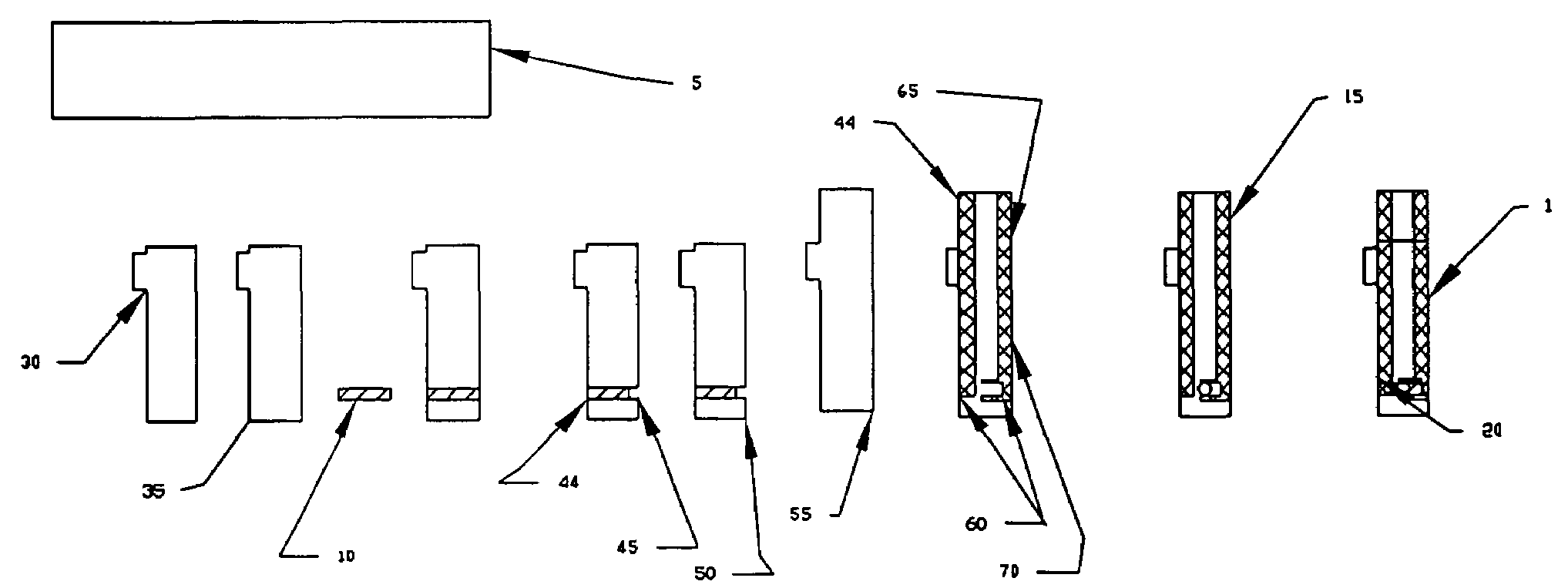
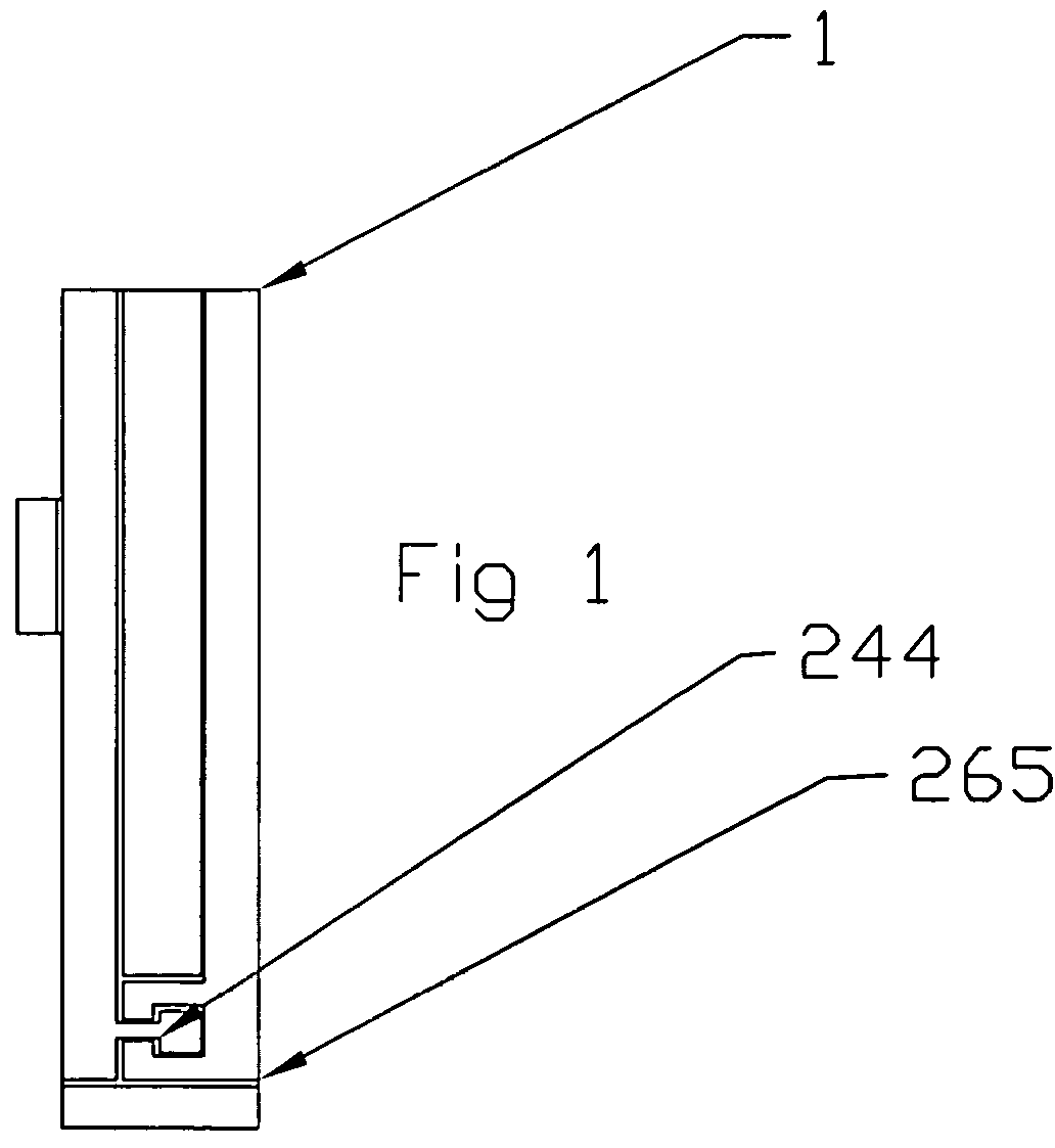
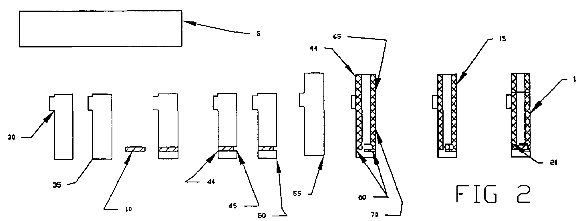

Image

  • Strip electrode with conductive nano tube printing
  • Strip electrode with conductive nano tube printing
  • Strip electrode with conductive nano tube printing

Examples


Embodiment Construction

[0037]Electrode Structure

[0038]In general, the strip electrode of the invention comprises a conductive electrode coated with a mixture of conductive carbon nanotubes or dispersion made from carbon nanotubes / antimony tin oxide, carbon nanotubes / platinum, or carbon nanotubes / silver or carbon nanotubes / silver-cloride, formed by coating the substrate with a conductive carbon nanotube solution similar to that found in conductive coatings such as described in U.S. patent application Ser. No. 2002 / 0143094, Polymer Nanocomposites and Methods of Preparation, to Conroy et al., U.S. patent application Ser. No. 2002 / 0035170, Electromagnetic Shielding Composite Comprising Nanotubes, to Glatkowski et al., U.S. patent application Ser. No. 2002 / 0180077, Carbon Nanotube Fiber-Reinforced Composite Structures for EM and Lightning Strike Protection, to Glatkowski et al., U.S. patent application Ser. No. 2003 / 0008123, Nanocomposite Dielectrics, to Glatkowski et al., U.S. patent application Ser. No. 2003...


PUM

PropertyMeasurementUnit
outer diameter sizeaaaaaaaaaa
outer diameteraaaaaaaaaa

Abstract

An electrochemical test device for determining the presence or concentration of an analyte in an aqueous fluid sample comprises a substrate comprising a non-conductive material; a working electrode comprising a conductive film formed at least with carbon nanotubes, the working electrode having a first electrode area, a first lead and a first contact pad; a counter electrode comprising a conductive film formed at least with carbon nanotubes; a reagent capable of reacting with the analyte to produce a measurable change in potential which can be correlated to the presence or concentration of the analyte in the fluid sample, the reagent overlaying at least a portion of the first electrode area of the working electrode; and a reference electrode comprising a conductive coating formed at least with carbon nanotubes, the reference electrode having a third electrode area at least a portion of which is overlaid with a reference material.

Description

REFERENCE TO RELATED APPLICATIONS[0001]This invention claims priority to U.S. Provisional Application No. 60 / 546,762 entitled Strip electrode with conductive nano tube printing and methods, filed on Feb. 23, 2004 which is entirely and specifically incorporated by reference.FIELD OF THE INVENTION[0002]The invention relates to a carbon nanotube electrode with a modified surface, to a method of production of such an electrode, and to the use of such an electrode in bioelectrochemistry. The electrode can be connected by a conductive carbon, silver ink or conductive carbon nanotube trace that is capable of conducting the electrons from the bioelectrochemistry reaction to a meter that reads the bioelectrochemistry result.BACKGROUND OF THE INVENTION[0003]Various electrochemical sensors are known which employ enzymes to sense the presence of a compound that serves as an enzyme substrate. As just one example, Nakamura U.S. Pat. No. 4,224,125 discloses an enzyme electrode system in which an e...

Claims


Application Information

Patent Timeline
Patent Type & Authority Patents(United States)
IPC IPC(8): G01N27/327G01N27/30B05D5/12C12Q1/00G01N27/26
CPCB82Y30/00C12Q1/002C12Q1/001Y10T428/265G01N27/308
Inventor DOUGLAS, JOEL S.
Owner DOUGLAS JOEL S MR
Learn More