
Press-fitting method and rectifying device having press-fitted member

a technology of pressing fitting and rectifying device, which is applied in the direction of magnetic circuit rotating parts, magnetic circuit shapes/forms/construction, manufacturing tools, etc., can solve the problems of reducing the tightness of physical and electrical connection between the inserting member and the receiving member, affecting the reliability and productivity of the rectifying device and the vehicular ac generator using the rectifying device, and affecting the quality of the produ

Inactive Publication Date: 2007-10-16
DENSO CORP
View PDF29 Cites 8 Cited by
  • Summary
  • Abstract
  • Description
  • Claims
  • Application Information

AI Technical Summary

Benefits of technology

[0009]The present invention therefore has an object to provide a press-fitting method for press-fitting an inserting member to a receiving member, by which galling is less likely to occur. The present invention has another object to provide a rectifying device in which a rectifying element is press-fitted in a radiation plate by the press-fitting method.
[0011]Further, a press-fitting method of the present invention includes punching an engaging hole in a receiving member having hardness higher than that of a receiving member while creating a hardened inner periphery surface on the receiving member, roughening the hardened inner periphery surface, and press-fitting the inserting member in the engaging hole.
[0013]The excess is released to the groove during the press-fitting of the inserting member in the receiving member. Thus, galling due to a hardened excess is less likely to occur, and physical and electrical connections between the inserting member and the receiving member is maintained. Furthermore, stress applied to the inserting member due to the hardened excess is reduced, and the productivity in the press-fitting process is maintained.
[0014]The inserting member is inserted from the side adjacent to the sheared surface. The hole is more precisely sized on this side than on the other side adjacent to the fractured surface. Thus, the inserting member can be more easily set in the receiving member on this side than on the other side upon the start of the press-fitting.
[0016]By using the inserting and receiving members and the press-fitting method, the reliability and productivity of the rectifying device and the vehicular AC generator using the rectifying device are improved.

Problems solved by technology

Reducing the size, the weight and the cost of the AC generator while improving the output power is a critical issue to maintain or improve the competitiveness in the market.
However, galling occurs in some materials in a pres-fitting process in which a base of the rectifying element is press-fitted in the hole formed in the radiation plate.
The excess is pushed in the inserting direction of the inserting member and hardened as the press-fitting process proceeds because space for releasing the excess is not provided.
As a result, the tightness of physical and electrical connection between the inserting member and the receiving member decreases.
Furthermore, large stress applied to the inserting member due to the hardened excess affects the productivity in the press-fitting process.

Method used


Image

  • Press-fitting method and rectifying device having press-fitted member
  • Press-fitting method and rectifying device having press-fitted member
  • Press-fitting method and rectifying device having press-fitted member

Examples


first embodiment

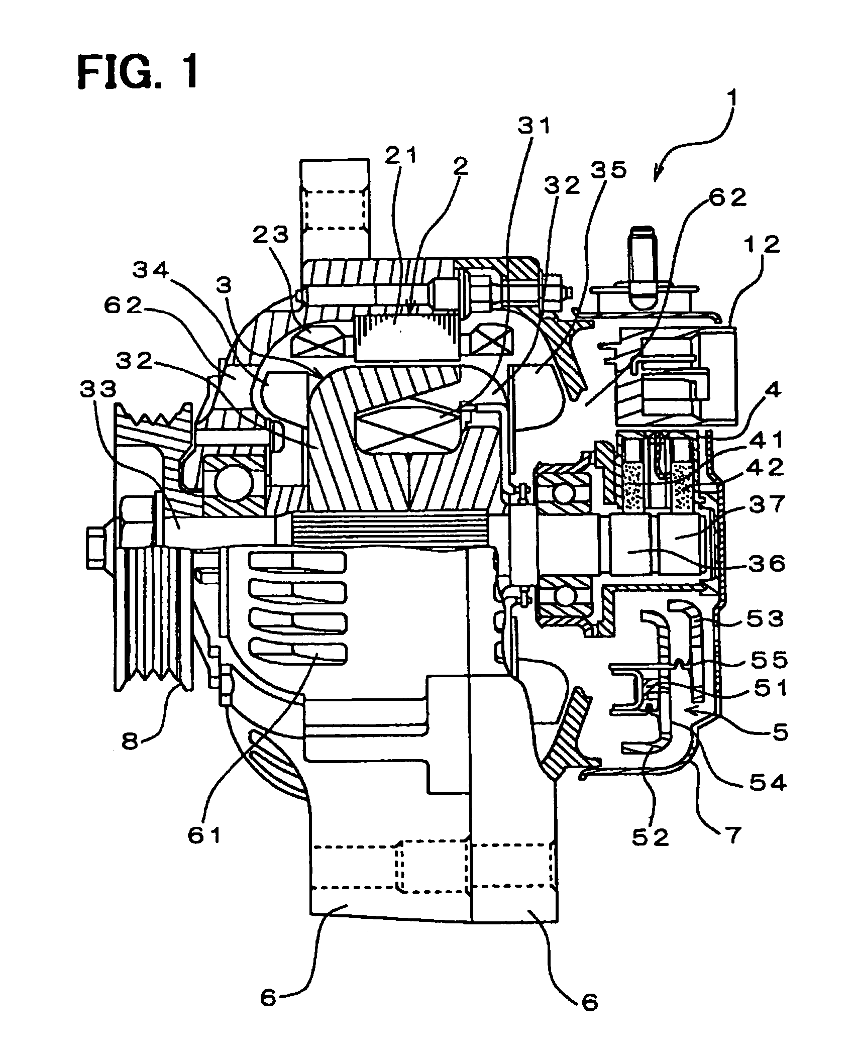
[0030]Referring to FIG. 1, an AC generator 1 for a vehicle includes a stator 2, a rotor 3, a brushing device 4, a rectifying device 5, a frame 6, a cover 7, and a pulley 8. The stator 2 has a stator core 21 and a three-phase stator coil 23 wound at a predetermined interval around slots formed in the stator core 21.

[0031]The rotor 3 has a field coil 31, pole cores 32, and a rotor shaft 33. The field coil 31 is constructed of an insulated copper wire concentrically wound in a cylindrical shape. Each pole core 32 has six claw poles and covers the field coil 31 from opposite sides. The rotor shaft 33 passes through the center of the pose cores 32.

[0032]An axial-flow type cooling fan 34 is welded to an end face of one of the pole cores 32 located adjacent to the pulley 8. The cooling fan 34 is used for blowing cooling air in the axial direction and in the radial direction. A centrifugal type cooling fan 35 is welded to an end face of the other pole core 32 for blowing cooling air in the ...

second embodiment

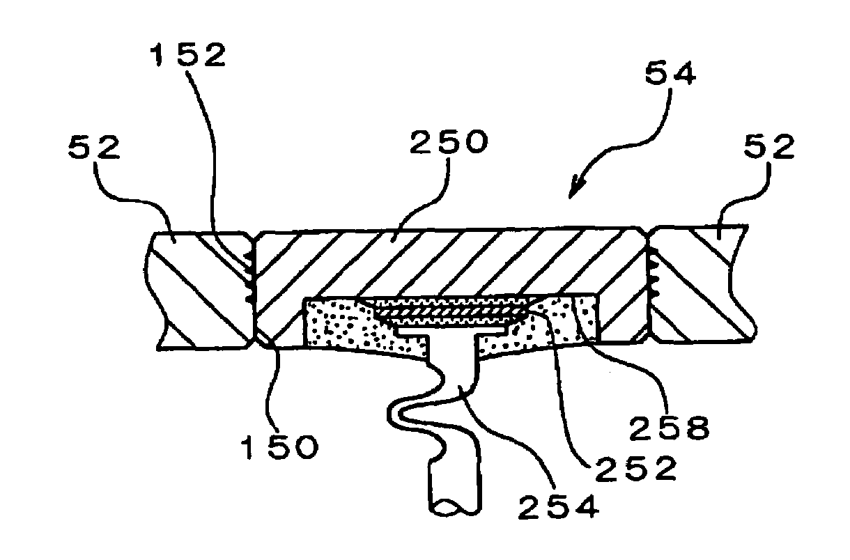
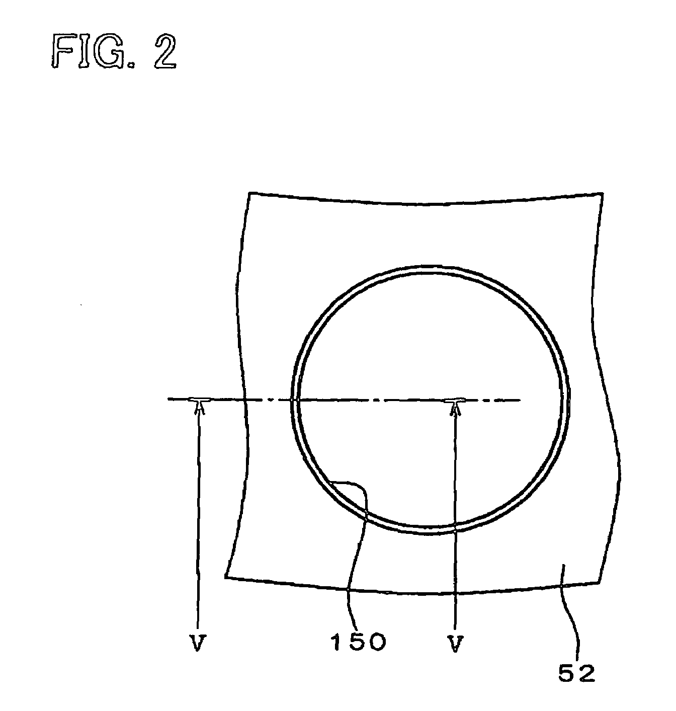
[0048]A groove 154 is formed in a spiral in the inner periphery of the positive-side radiation plate 52 as shown in FIG. 7. The rest of configuration of the radiation plate 52 is the same as the first embodiment. The groove 154 performs the same function as the multiple grooves 152 of the first embodiment. It functions as if it is constructed of multiple grooves with respect to the direction in which the rectifying element 54 is inserted in the radiation plate 52. Thus, an excess produced by the press-fitting of the rectifying element 54 can be dividedly released to the groove 154.

[0049]The groove 154 has an advantage over the grooves 152 in the groove forming step. In the groove forming step of the groove 154, only one groove is formed in a series of machine works while multiple series of machine works are required to form the grooves 152. Namely, the groove forming step of the groove 154 is simplified in comparison with that of the grooves 152.

third embodiment

[0050]Referring to FIGS. 8 and 9, multiple grooves 156 are formed in the inner periphery of the positive-side radiation plate 52. The grooves 156 are formed in the direction that the engaging hole 150 is formed and apart from each other in the circumferential direction of the radiation plate 52. The rest of configuration is the same as the first embodiment.

[0051]An excess produced during the press-fitting of the rectifying element 54 in the hole 150 is released into the grooves 156. Thus, the excess is less likely to build up and galling between the radiation plate 52 and the rectifying element 54 is reduced. By forming the grooves 156 in the entire inner periphery of the radiation plate 52 as shown in FIG. 8, the excess is effectively released into the grooves 156.

[0052]It is preferable that each groove 156 has a depth of about 0.1 mm and a width of about 0.1 mm. If the inner diameter φ1 of the engaging hole 150 is about 13 mm, it is preferable that about 40 to 78 grooves 156 are p...


PUM

PropertyMeasurementUnit
Diameteraaaaaaaaaa
Hardnessaaaaaaaaaa

Abstract

In a rectifying device for a vehicular AC generator, a rectifying element is press-fitted in a positive-side radiation plate. The radiation plate is prepared in a predetermined shape and an engaging hole is punched in the radiation plate. Four grooves are formed in an inner periphery of the radiation plate created by the hole. The rectifying element is press-fitted in the hole while an excess produced between the rectifying element and the inner periphery of the radiation plate is released into the grooves.

Description

CROSS REFERENCE TO RELATED APPLICATION[0001]This application is based on and incorporates herein by reference Japanese Patent Application No. 2002-364485 filed on Dec. 16, 2002.FIELD OF THE INVENTION[0002]The present invention relates to press-fitting method and a rectifying device having a press-fitted member.BACKGROUND OF THE INVENTION[0003]An AC generator generates power by using the driving force transmitted from an engine, charges a battery, and supplies power to various kinds of electronic parts. Reducing the size, the weight and the cost of the AC generator while improving the output power is a critical issue to maintain or improve the competitiveness in the market.[0004]A method for manufacturing a rectifying device for an AC generator is proposed in U.S. Pat. Document No. U.S. Pat. No. 5,828,564 (JP-A-10-242671). In this method, a rectifying element is press-fitted in a through hole formed in a radiation plate. The rectifying element is fixed and electrically connected to t...

Claims


Application Information

Patent Timeline
IPC IPC(8): H02K11/04H02M1/00B23P11/00B23P19/02H01L23/36H01L23/48H01L23/492H01L25/11H02M7/04
CPCB23P11/00H01L24/01H01L25/115H02K11/046H01L23/492Y10T29/49139H01L2924/01004H01L2924/01029H01L2924/01033H01L2924/01078H01L2924/01082H01L2924/01006H01L2924/01023H01L2224/45147Y10T29/49128H01L2924/00014H01L2924/00H01L2224/48H01L2924/00011H02K11/05
Inventor FUJIOKA, TATSUMI
Owner DENSO CORP
Learn More