Eureka AIR delivers breakthrough ideas for toughest innovation challenges, trusted by R&D personnel around the world.

Optical connection for interferometry

a technology of optical connection and interferometer, which is applied in the field of optical connection for interferometer, can solve the problems of reducing the fidelity of heterodyne interferometry measurement, difficult to predict these effects in advance or compensate, and affecting the performance of the interferometer, so as to facilitate the process of lithography, high-precision manufacturing, and related small-scale activities. the effect of improving the degree of precision that can be obtained in frequency measuremen

Active Publication Date: 2007-10-02
ZYGO CORPORATION
View PDF26 Cites 7 Cited by
  • Summary
  • Abstract
  • Description
  • Claims
  • Application Information

AI Technical Summary

Benefits of technology

The invention features a method and apparatus for generating a beam with two different polarization components and rotating the polarization of each component using optical rotators. This allows for the creation of a heterodine beam or a homodyne beam with a second frequency that is different from the first frequency. The apparatus includes a laser module, an interferometer head, and an optical connection between them. The technical effects of this invention include improved accuracy and stability in position measurement and improved laser efficiency.

Problems solved by technology

Unfortunately, the generation of the heterodyne beam may produce heat and mechanical vibrations that can detrimentally affect the performance of the interferometer.
Unfortunately, polarization mixing and birefringent optical effects, which disproportionately affect one polarization, when the heterodyne beam is transmitted to the interferometer can reduce the fidelity of the heterodyne interferometry measurement.
Furthermore, such effects may vary based on temperature, mechanical vibrations, and other surrounding conditions, thus making it difficult to predict these effects in advance or to compensate for them.

Method used


Image

  • Optical connection for interferometry
  • Optical connection for interferometry
  • Optical connection for interferometry

Examples


Embodiment Construction

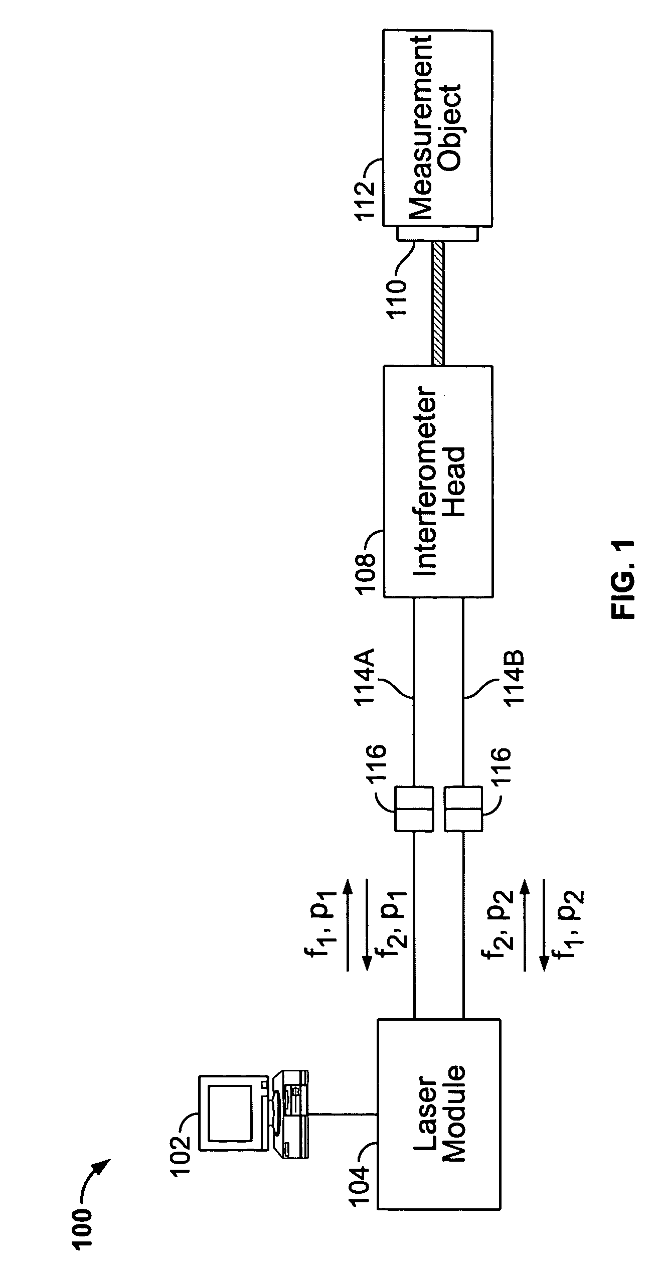
[0048]FIG. 1 depicts a system 100 for performing heterodyne interferometry measurements. In the depicted embodiment, system 100 includes a computer 102, a laser module 104, and an interferometer head 108 connected to laser module 104 by two connections 114A and 114B formed using optical transmission media, henceforth referred to as optical paths 114A and 114B or collectively as optical paths 114. The interferometer head 108 permits interference measurements using light reflected from a reflector 110 (e.g., a plane mirror or a retroreflector) attached to a measurement object 112. This allows the position of measurement object 112 to be determined with a high degree of precision, which may in turn facilitate processes such as lithography, high-precision manufacturing, and related small-scale activities. For example, system 100 might be used to measure the location of a wafer stage or a mask used in semiconductor fabrication.

[0049]Heterodyne interferometry involves the use of a laser s...


PUM


Abstract

A method including: (i) directing a beam to an interferometer head using an optical connection, the beam including a first beam component having a first polarization and a first frequency and a second beam component having a second polarization different from the first polarization and a second frequency; (ii) rotating the polarization of the first beam component to the second polarization; (iii) rotating the polarization of the second beam component to the first polarization; and (iv) returning the beam with the rotated polarizations from the interferometer head using the optical connection. For example, the step of directing may include: directing the first beam component into a first fiber of the optical connection; and directing the second beam component into a second fiber of the optical connection. The first beam component may be returned using the second fiber, and the second beam component may be returned using the first fiber.

Description

TECHNICAL FIELD[0001]This invention relates generally to interferometry, e.g., heterodyne interferometry, and more particularly to compensation of optical perturbations in an interferometry path from a remote source to a interferometer.BACKGROUND[0002]In heterodyne interferometry, a laser source generates a beam that includes two polarizations separated slightly in frequency (a “heterodyne beam”). The interference between the two polarizations in an interferometer provides a highly accurate measurement of the position of a measurement reflector relative to a reference reflector. By coupling the measurement reflector to a measurement object, the relative position of the measurement object can be determine with a similar degree of precision. Unfortunately, the generation of the heterodyne beam may produce heat and mechanical vibrations that can detrimentally affect the performance of the interferometer. The laser source may be placed at some distance from the interferometer in order t...

Claims


Application Information

Patent Timeline
Patent Type & Authority Patents(United States)
IPC IPC(8): G01B11/02
CPCG01B9/02007G01B9/02003G01B2290/70
Inventor TOWNLEY-SMITH, PAUL A.KONDIS, JOHN
Owner ZYGO CORPORATION
Why Eureka
Eureka Blog
Learn More