
Removable memory media with integral indicator light

a technology of memory media and indicator light, which is applied in the field of removable memory media, can solve the problems of affecting the operation of the removal of the personal mass storage memory media, affecting the success of the operation, and affecting the operation of the flash module,

Inactive Publication Date: 2007-10-02
MICRON TECH INC
View PDF110 Cites 21 Cited by
  • Summary
  • Abstract
  • Description
  • Claims
  • Application Information

AI Technical Summary

Benefits of technology

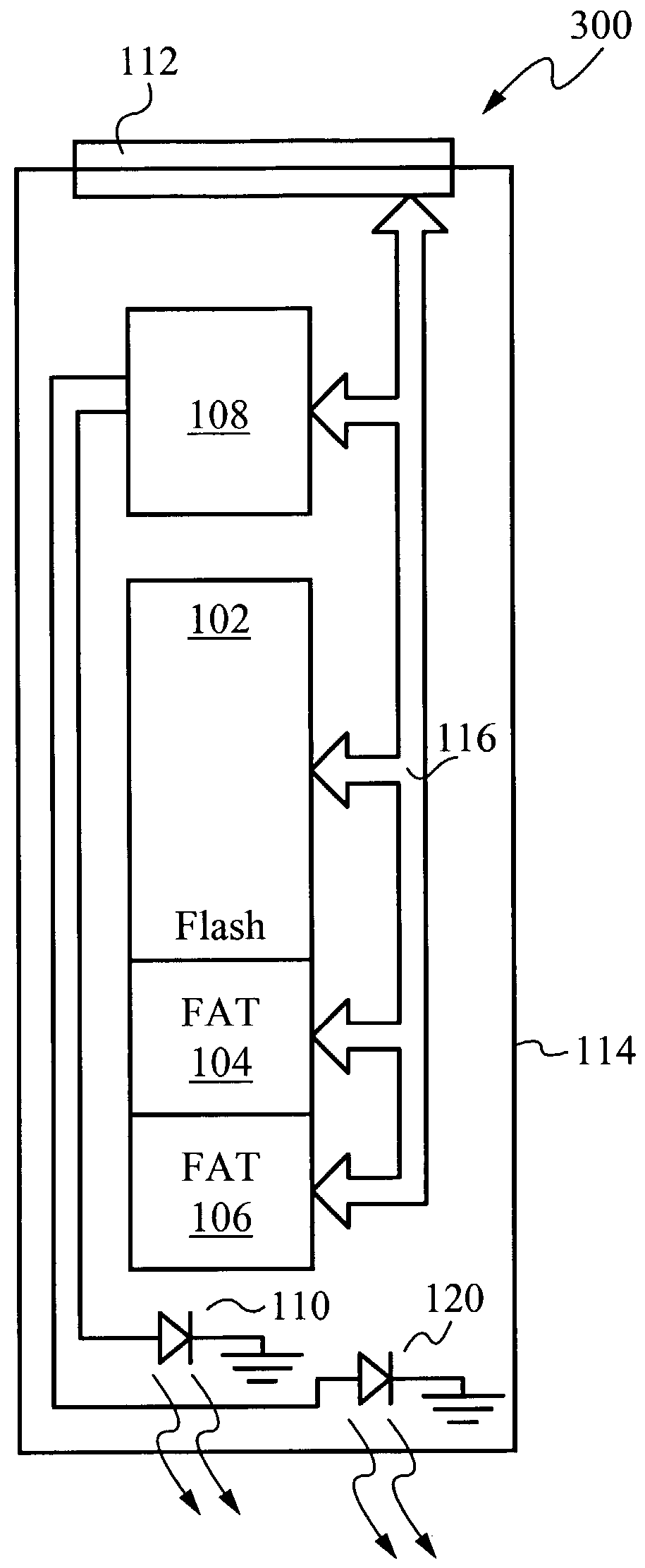
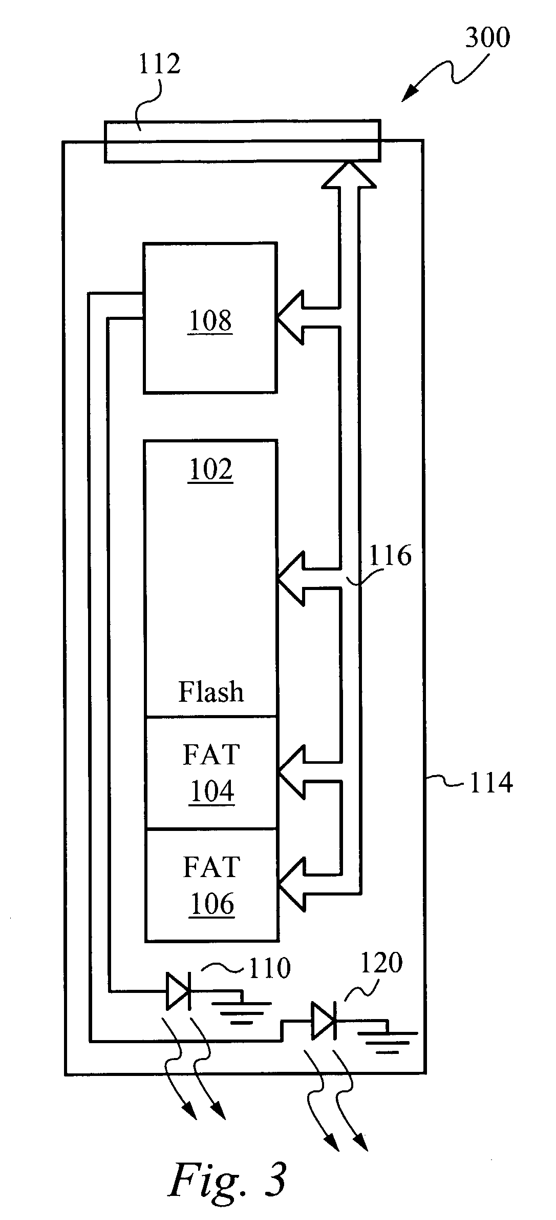
The present invention is for a flash memory module with an indicator light. The flash memory module has multiple electrical contacts that connect to a host device, and includes multiple flash memory cells. The indicator light indicates if the flash memory module is being accessed. The flash memory module is made of a light-transmissive material, such as transparent plastic. The indicator light can be a surface mount LED positioned at the end of the flash memory module. The flash controller can generate signals to advise the host device that the flash memory module is operating, or that it is close to the maximum limit of program-erase operations or spares. These signals can be generated by flashing the LED or by altering the cadence of the flashing. The technical effect of this invention is to provide a convenient and reliable way to access and manage flash memory modules in a host device.

Problems solved by technology

It is well recognized that removing a personal mass storage memory media can interfere with a successful operation.
It is further recognized that removing the media during an access can corrupt the data.
As is well known, writing data to a flash module takes a finite amount of time that is generally long when compared to writing data to conventional volatile memory, such as addressable RAM, SRAM, DRAM or to a cache.
When this happens the data file is typically corrupted.
It is known that the life time for flash memory cells is limited.
The host digital device is not informed and has no means to learn that the integral controller is modifying data on the flash memory module.
If a data file is corrupted, it is possible that only that file is corrupted.
However, if the flash memory module is removed while the FAT tables are being modified, it is generally not possible to retrieve any data from the flash module.
Typically, in such a circumstance, the entire flash module must be reformatted so that all the data would be permanently lost.
It may be possible to use a software application such as Norton™ utility to retrieve any non-corrupted file, however, the success rate of such an operation is not satisfactory.
Additionally, because flash memory cells have a limited life time, and because it is generally not possible for a user to know how many times a particular memory cell or group of memory cells has been written, it is possible for a host system to attempt to program data to a flash cell or a plurality of flash cells that have exceeded their useful life and are no longer functional.
When this occurs, the data being written can become corrupted and permanently lost.
Also, the performance of a flash cell degrades as the number of program-erase cycles to that cell passes a threshold limit.
For certain critical systems, such as a flash module in a flight recorder, such degradation cannot be tolerated.
This problem is particularly onerous for systems where the flash module is continuously accessed, for example by a server.
In such a system, as the number of spares is reduced and becomes zero, the system becomes prone to a catastrophic failure when a program-erase operation is attempted while no goods flash blocks remain.

Method used


Image

  • Removable memory media with integral indicator light
  • Removable memory media with integral indicator light
  • Removable memory media with integral indicator light

Examples


Embodiment Construction

[0019]FIG. 1 shows a flash memory module 100 according to the present invention. The flash memory module 100 includes an array of flash memory cells 102. A portion of the array is provided for storing the FAT tables 104 and 106. An integral controller 108 is configured to control the flash memory cells 102 and the FAT tables 104 and 106. The integral controller 108 is coupled to the flash memory cells 102 and the FAT tables 104 and 106 via a bus 116. The integral controller 108 also preferably performs memory maintenance operations, such as wear leveling activities or erasing replaced data to provide blocks for storing additional data. While the architecture of the flash memory module 100 is shown, this architecture is representative only and any conventional architecture for flash memory can be used according to the teachings of this invention.

[0020]An LED 110 is coupled under control of the integral controller 108. Whenever the flash memory module 100 is accessed for reading or pr...


PUM


Abstract

A flash memory module includes an integral indicator light. The module alternatively includes a plurality electrical contacts which electrically interface to a host digital device. The module includes a plurality of flash memory cells. The cells are controlled by an integral controller. The indicator light is controlled by the controller. The indicator light indicates whether the flash memory module is being accessed. Alternatively, the indicator light indicates that the flash memory module should be replaced. A housing for the module is preferably light transmissive material, and preferably a transparent plastic. A proximal end of the module includes the electrical contacts and is inserted into the host. The indicator light is preferably a surface mount LED and is positioned adjacent the distal end of the flash memory module to be seen through the transparent plastic. Alternatively, the controller generates an electronic signal which is coupled to the host.

Description

CROSS REFERENCE TO RELATED APPLICATIONS[0001]This application claims priority of and incorporates by reference U.S. Provisional Patent Application Ser. No. 60 / 359,468 filed Feb. 22, 2002, and entitled Removable Memory Media With Integral Indicator Light.FIELD OF THE INVENTION[0002]This invention relates to the field of removable memory media. More particularly, this invention relates to the removable memory that includes an integral indicator light to indicate that the memory is in use.BACKGROUND OF THE INVENTION[0003]Removable personal mass storage memory media has been used for many years. Examples of such devices in include floppy discs, read-write CD-ROMs, and flash memory modules. It is well known that the drive and controller units that accept floppies and CD-ROMs include a controllable light that indicates whether the drive is writing to or reading from the media. The system activates the light to advise an operator that the media is being accessed so that the operator does n...

Claims


Application Information

Patent Timeline
Patent Type & Authority Patents(United States)
IPC IPC(8): G08B21/00G06K19/07G11C16/34G11C29/44
CPCG11C29/44G11C16/349G11C16/04
Inventor ESTAKHRI, PETRO
Owner MICRON TECH INC
Learn More