
Automated method and apparatus for processor thermal validation

a technology of thermal validation and automatic method, applied in the direction of electrical apparatus casing/cabinet/drawer, fire alarm, instruments, etc., can solve the problems of microprocessor failure, internal breakdown of processor circuit, and excess hea

Inactive Publication Date: 2007-09-25
INTEL CORP
View PDF37 Cites 68 Cited by
  • Summary
  • Abstract
  • Description
  • Claims
  • Application Information

AI Technical Summary

Benefits of technology

The patent describes a method and apparatus for automatically performing thermal validation of microprocessors. The invention aims to prevent processor failure due to excess heat. The technical effects of the invention include reducing the risk of processor failure, ensuring optimal cooling of components, and validating the thermal solution of a platform to prevent damage to the processor. The invention uses statistical data and external instrumentation to verify the thermal solution, which is a time-consuming and expensive process. The invention provides a faster and more cost-effective way to verify the thermal solution of a platform, ensuring processor longevity.

Problems solved by technology

Excess heat is one of the primary causes of failure for microprocessors.
Excessive heat results in internal breakdown of the processor circuits, eventually resulting in failure.
Operation outside of the functional temperature range can degrade system performance, cause logic errors, or cause component and / or system damage.
Temperature exceeding the maximum operating limit of a component may result in irreversible changes in the operating characteristics of the component.
While this is generally not as much of an issue for desktop computer systems, which typically provide thermal solutions having large cooling margins, such large cooling margins are not realizable for laptop and notebook computers.
This type of thermal solution verification testing is both expensive and time-consuming.

Method used


Image

  • Automated method and apparatus for processor thermal validation
  • Automated method and apparatus for processor thermal validation
  • Automated method and apparatus for processor thermal validation

Examples


Embodiment Construction

[0015]Embodiments of methods and apparatus for automatically performing processor thermal validation are described herein. In the following description, numerous specific details are set forth to provide a thorough understanding of embodiments of the invention. One skilled in the relevant art will recognize, however, that the invention can be practiced without one or more of the specific details, or with other methods, components, materials, etc. In other instances, well-known structures, materials, or operations are not shown or described in detail to avoid obscuring aspects of the invention.

[0016]Reference throughout this specification to “one embodiment” or “an embodiment” means that a particular feature, structure, or characteristic described in connection with the embodiment is included in at least one embodiment of the present invention. Thus, the appearances of the phrases “in one embodiment” or “in an embodiment” in various places throughout this specification are not necess...


PUM

PropertyMeasurementUnit
temperaturesaaaaaaaaaa
thermal stressaaaaaaaaaa
power dissipationaaaaaaaaaa

Abstract

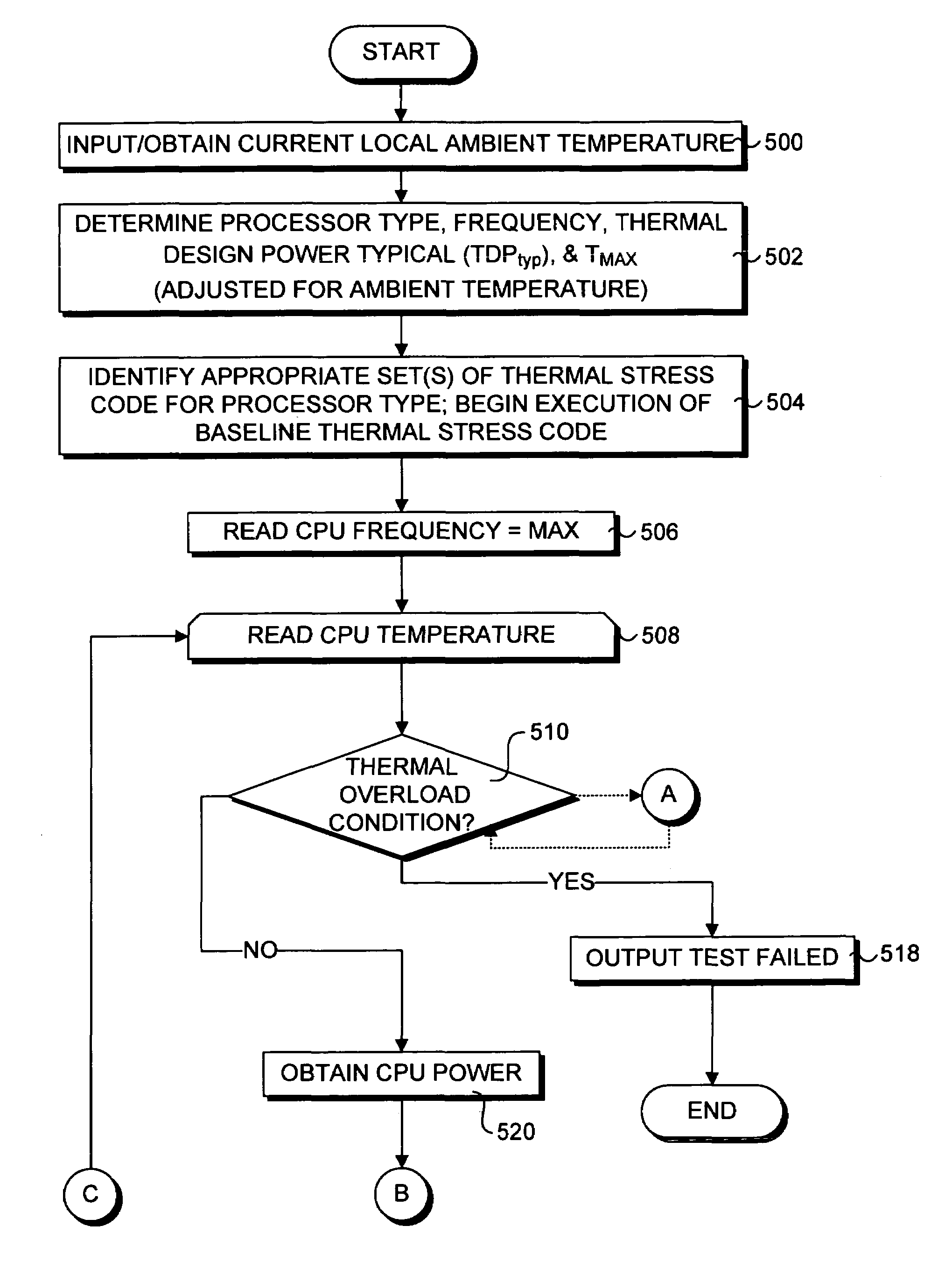
A method and corresponding software for automatically validating a computer platform thermal solution. An application program is employed to selectively execute thermal stress code to cause the platform's processor to dissipate an amount of power corresponding to a predetermined value, such as a thermal design power dissipation value specified by the processor's manufacturer. In one embodiment, tests are performed while operating at this power dissipation level to determine if a thermal overload condition exists, which may be determined by the processor's temperature, an indication that the processor is throttled, or a signal provided by the processor indicating the processor has detected a thermal overload condition. In another embodiment, a thermal resistance value is calculated based on the processor power dissipation, the temperature of the processor, and the ambient temperature of the test environment. In one embodiment the entire validation process is automatically performed by the application program without requiring any extraneous test equipment or temperature probes.

Description

FIELD OF THE INVENTION[0001]The field of invention relates generally to thermal validation of integrated circuits and, more specifically but not exclusively relates to a method and apparatus for automatically performing thermal validation of microprocessors.BACKGROUND INFORMATION[0002]Excess heat is one of the primary causes of failure for microprocessors. Generally, the life of a microprocessor is a function of the thermal load applied during its use. Excessive heat results in internal breakdown of the processor circuits, eventually resulting in failure. With the introduction of processors with sub-micron circuit elements, ever-increasing transistor count (e.g., 42 million transistors for an Intel Pentium 4™ processor) and operating speed, the problem of preventing processor failure due to excess heat is exacerbated.[0003]The objective of thermal management is to ensure that the temperature of all components in a system are maintained with their functional temperature range. Within...

Claims


Application Information

Patent Timeline
Patent Type & Authority Patents(United States)
IPC IPC(8): G01K17/00G01K7/10G01K7/42
CPCG01K7/42
Inventor HERMERDING, II, JAMES G.
Owner INTEL CORP
Learn More