
Aircraft landing gear initial touch-down velocity monitor

a technology of initial touchdown and monitor, which is applied in the direction of instruments, mechanical equipment, transportation and packaging, etc., can solve the problems of increasing the pressure within the shock absorber, the aircraft has no device installed to monitor the individual touch-down velocity of the landing gear, and the aircraft cannot monitor the individual landing gear touch-down speed, etc., to achieve the effect of better monitoring the utilization of the aircraft landing gear system

Active Publication Date: 2007-09-25
NANCE C KIRK
View PDF25 Cites 27 Cited by
  • Summary
  • Abstract
  • Description
  • Claims
  • Application Information

AI Technical Summary

Benefits of technology

"The present invention provides a method and apparatus for monitoring the landing gear of an aircraft during initial contact with the ground. The invention measures the extension of the telescopic strut and the rotation of the linkage members to determine the touch-down velocity of the aircraft. This information can be used to better monitor the utilization of the aircraft landing gear system and to compare asymmetrical touch-down velocities of each landing gear. The invention also compensates for the influence of pre-charge pressure and frictional forces within the landing gear system to better evaluate its fatigue life. Overall, the invention provides a tool to better manage and improve the performance of the aircraft landing gear system."

Problems solved by technology

Aircraft have limitations regarding the maximum allowable force the aircraft landing gear and other supporting structures of the aircraft can safely absorb when the aircraft lands.
This causes an overweight landing event.
These limitations assume the aircraft is landing with each of the main landing gear simultaneously touching the ground and the landing force being equally distributed between the two main landing gears.
Currently there are no devices installed on aircraft to monitor individual landing gear touch-down velocities.
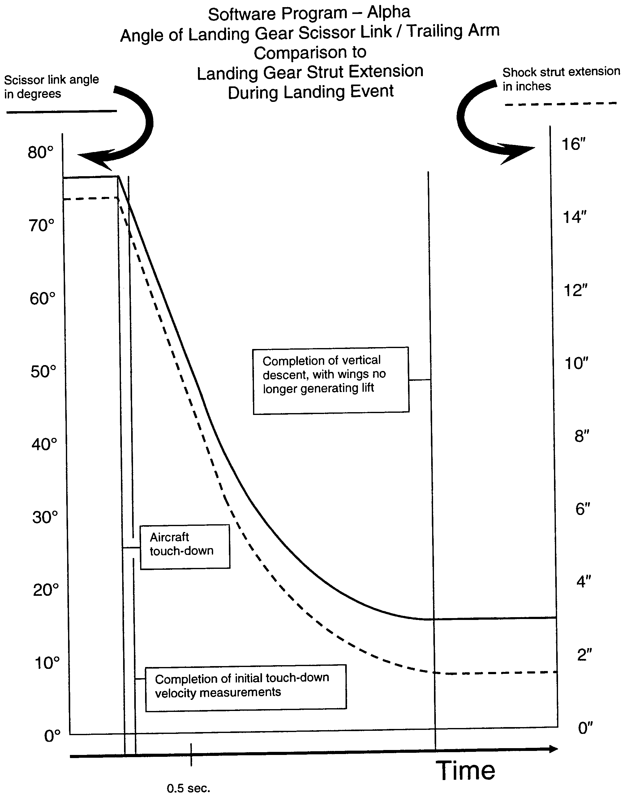
As the landing gear comes into initial contact with the ground, the strut begins to compress, thereby increasing the pressure within the shock absorber.
Unfortunately the range-finder devices do not measure the initial touch-down velocity of each respective landing gear, as they come into contact with the ground.
Though the approach may appear valid, it is subject to error by its inability to verify, at any given landing event, the exact proportion of gas volume in relation to hydraulic oil volume, within the landing gear strut.
Mistakenly assuming the landing gear has lost nitrogen gas, the technician adds additional gas to the strut, thus the landing gear strut is now over-charged with gas.
The now changed and unknown volume of gas being compressible and that variance in volume of gas as compared to the unknown volume of non-compressible hydraulic oil having changed, would thereby vary the compression rate of the landing gear strut and generate errors in the velocity calculation.
Attempts to determine initial touch-down velocity of the landing gear strut would be subject to errors caused by the friction of the strut seals distorting pressure measurements and delaying any increases in internal landing gear strut pressure.
These delays in any increase in strut pressure due to strut seal friction would distort the accuracy of a direct comparison of rate of internal pressure increases to strut compression.
Additional measurements, taken after initial rotation, are considered inaccurate due to velocity reduction caused by additional opposing pressure build-up in the strut.

Method used


Image

  • Aircraft landing gear initial touch-down velocity monitor
  • Aircraft landing gear initial touch-down velocity monitor
  • Aircraft landing gear initial touch-down velocity monitor

Examples


example

[0064]Va=(m+mpc+mf)⁢V2mVa=(21⁢,⁢000+1⁢,⁢407+138)×2521⁢,⁢000Va=22⁢,⁢545×2521⁢,⁢000Va=563⁢,⁢62521⁢,⁢000Va=26.894Va=5.181⁢⁢fps

[0065]Considering the weight / mass applied to any one landing gear, that mass will increase as the wing lift reduces, and additional load is transferred to that landing gear. The opposing internal strut pressure within the landing gear will increase due to the shock absorbing characteristics of the strut, thereby additionally reducing descent velocity.

[0066]Determining the change and rate of change in Kinetic Energy throughout the un-loading of wing lift requires determination of the rate the weight / mass increases, compared to the reducing rate of descent velocity. Once initial touch-down velocity measurements have been made, additional calculations are be made to determine the amount and rate of weight / mass increases and corrected for distortions caused by increasing opposing pressure within the landing gear strut. These relationships are recorded and compared t...


PUM


Abstract

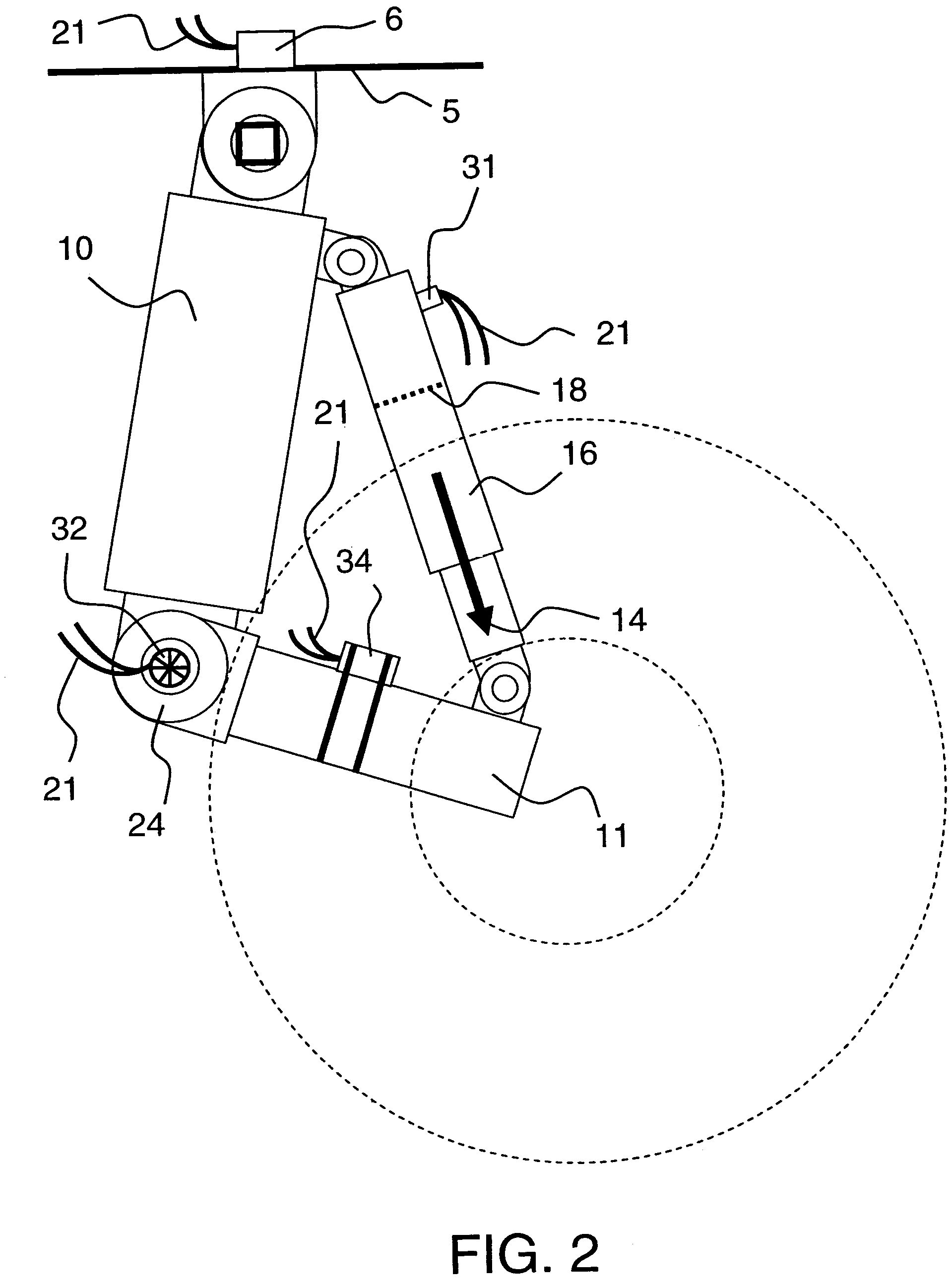
A system for use in monitoring, measuring, computing and displaying the initial touch-down descent velocity experienced while aircraft are executing either normal, overweight or hard landing events. Pressure sensors and motion sensors are mounted in relation to each of the landing gear struts to monitor, measure and record the impact loads and aircraft touch-down vertical velocities experienced by landing gear struts, as the aircraft landing gear initially comes into contact with the ground. Velocity adjustments are made to correct for errors caused by landing gear per-charge pressure and landing gear strut seal friction. The system also measures the landing loads experienced by each landing gear strut during the landing event and determines if aircraft limitations have been exceeded.

Description

[0001]This application is a continuation-in-part of application Ser. No. 11 / 092,020, filed Mar. 29, 2005 now U.S. Pat. No. 7,193,530 and also claims the benefit of provisional patent application Ser. No. 60 / 688,624, filed Jun. 8, 2005.BACKGROUND OF THE INVENTION[0002]An aircraft is typically supported by plural pressurized landing gear struts. Each landing gear strut is designed much like, and incorporates many of the features of a typical shock absorber. Designs of landing gear incorporate moving components which absorb the impact force of landing. Moving components of an aircraft landing gear shock absorber are commonly telescopic elements connected by a scissor-link. The scissor-link incorporates a hinge, allowing the arms of the scissor link to move with the telescopic elements of the strut. An alternate type of landing gear incorporates a trailing arm design, where the main supporting element of the landing gear is hinged with a trailing arm. The hinge design of major elements ...

Claims


Application Information

Patent Timeline
Patent Type & Authority Patents(United States)
IPC IPC(8): G08B21/00
CPCB64D45/00B64D2045/008
Inventor NANCE, C. KIRK
Owner NANCE C KIRK
Learn More