
Nonaqueous-electrolyte secondary battery and method of manufacturing the same

Inactive Publication Date: 2007-09-18
MURATA MFG CO LTD
View PDF5 Cites 3 Cited by
  • Summary
  • Abstract
  • Description
  • Claims
  • Application Information

AI Technical Summary

Benefits of technology

[0013]The invention has been achieved in consideration of the above problems and its object is to provide a lithium ion battery with high productivity and excellent in hermeticity inside the battery covered with a package member by means of preventing sealing failures caused by a gap occurred between sides of a lead electrode and the package member, and a method of manufacturing the same.
[0019]A method of manufacturing another nonaqueous-electrolyte battery according to the present invention comprises steps of fusing a sealing member, whereby the sealing member made of a thermoplastic material is disposed in a predetermined position of a lead electrode, pressure is applied to at least the sealing member from the outside, a stripping sheet made of a material such that at least its surface does not adhere to the sealing member, is inserted between the heater and the sealing member, and of separating the stripping sheet from the package member, whereby after sealing member can spread between the lead electrode and the package member without a gap by heating and fusing the sealing member, the stripping sheet is separated from the heater, then after the fused sealing member re-solidifies to be made in a solid state.
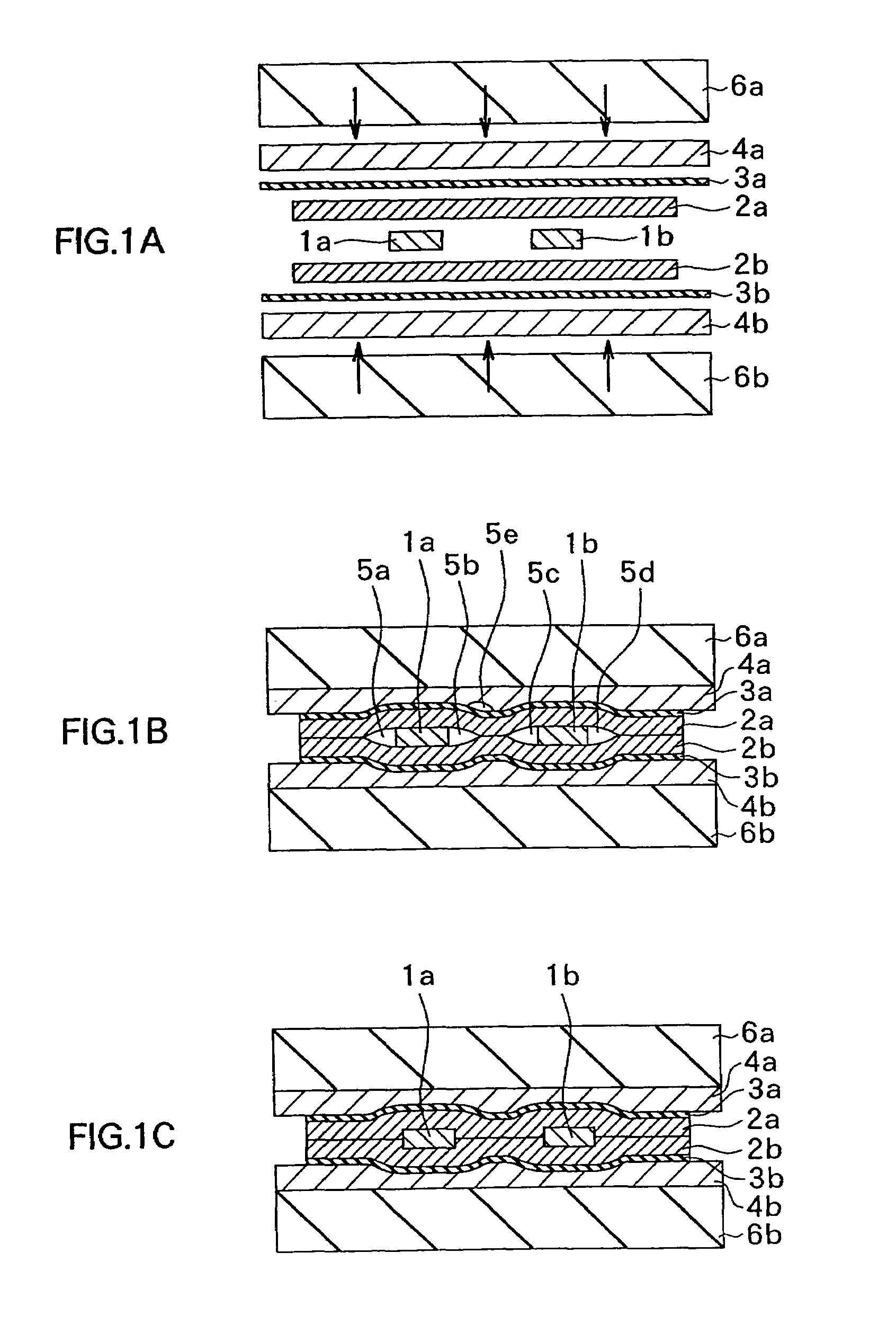
[0022]Additionally, since the stripping sheet has a sheet-like shape unlike the case it is annexed to the surface of the heater in a flat shape the heater presses the stripping sheet in a manner of shaping along with a concave-convex shape of the sealing member, thereby, even if after the sealing member fuses and spreads between the package member, the package member and the sealing member are soon stripped from the heater with the stripping sheet, the shape of the sealing member and the state of the lead electrode can be maintained until the sealing member re-solidifies to be made in a solid state.
[0023]For this reason, without letting the heater is repeated to heat and cool itself, when heating generated is necessary, the heater pressed the package member and the sealing member in order to fuse the sealing member, then on the sealing member fuses enough, the heater is separated from the package member covered with the stripping sheet and the sealing member, which gives the time when the sealing member cools and re-solidifies at room temperature, or by forced cooling wind. This also maintains the shape of the sealing member even if the heater is apart when the sealing member does not solidify yet. From this point, the stripping sheet is desirable used in a sheet-like state, which can be separated from the heater rather than coating on the surface of the heater.

Problems solved by technology

However, in the conventional sealing structure and method of manufacturing the same using the adhesive material as described above, there are problems such that even if the package members can be completely sealed to principal surfaces of the lead electrodes, gaps are easy to be produced between sides of the lead electrodes and the package members, which causes an incomplete sealing state (or hermeticity decrease), thereby, insides of the batteries are susceptible to influence of temperature variations or influence from the outside, and by secular change in the batteries, the insides of the batteries deteriorates rapidly, which results in decrease of electromotive force and reduction of durability.
Additionally, such batteries occurred the gaps causing degradation of battery capability, must be treated as a nonconforming battery, which results in productivity decrease.

Method used


Image

  • Nonaqueous-electrolyte secondary battery and method of manufacturing the same
  • Nonaqueous-electrolyte secondary battery and method of manufacturing the same
  • Nonaqueous-electrolyte secondary battery and method of manufacturing the same

Examples


Embodiment Construction

[0038]Embodiments of the invention will be described in detail hereinbelow by referring to the drawings.

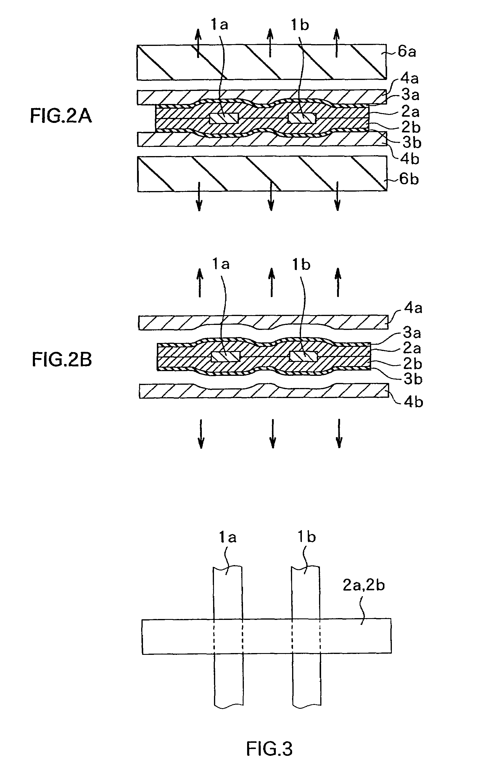
[0039]FIGS. 1A-1C and 2A-2B are schematic views showing a method of manufacturing a lithium ion polymer secondary battery relative to an embodiment of the present invention. FIGS. 1A-1C and 2A-2B shows a condition observed in a direction shown as an arrow A in FIG. 4. FIG. 3 is a view showing a two-dimensional schematic structure of sealed ends of sealing package members observed in a direction shown as an arrow B in FIG. 4. The structure of a sealed part of the lithium ion polymer secondary battery relative to the embodiment of the present invention is also explained hereinafter because it is embodied by the manufacturing method relative to the embodiment of the present invention. Additionally, in FIGS. 1A-1C, 2A-2B and detailed explanation based on the above-mentioned drawings, for avoiding complicated drawings and explanation, a sealing step in the method of manufacturing the l...


PUM


Abstract

To offer excellent hermeticity inside a battery having high productivity and being covered with package members by means of solving a problem such as sealing failures caused by gaps between sides of lead electrodes and the package members in sealing parts, in which the lead electrode to be disposed. During a step of sealing between ends of the package members and the lead electrodes by fusing the sealing members, or during a step of adhering the fused sealing members to the lead electrodes, stripping sheets made of a material such that the fused sealing members does not adhere to heaters, are inserted between the package members, or the sealing members and the heaters. Accordingly, even if the fused sealing members are forced out from ends of the package members, or leaked toward the outside, the sealing members does not adhere to surfaces of the heaters or crumble their shapes.

Description

RELATED APPLICATION DATA[0001]The present application claims priority to Japanese Application No. P2000-081578 filed Mar. 23, 2000, and is a divisional of U.S. application Ser. No. 09 / 814,632 filed Mar. 22, 2001 now U.S. Pat. No. 6,689,177, both of which are incorporated herein by reference to the extent permitted by law.BACKGROUND OF THE INVENTION[0002]The present invention relates to a lithium ion battery such as a lithium ion polymer secondary battery having a gel-type or plastic macromolecular electrolyte layer, and a method of manufacturing the same.[0003]In recent years, accompanying by a situation that portable small electric equipment such as small, lightweight cellular phones or portable computers has been popularized, second batteries having small, reliable output characteristics and capable of longtime use by recharging many times such as nickel-cadmium batteries, nickel-hydrogen batteries and lithium ion batteries has been studied and developed vastly as an electric sour...

Claims


Application Information

Patent Timeline
IPC IPC(8): H01M2/02H01M6/18H01M10/05H01M10/0525H01M10/0565H01M10/058H01M10/0585H01M10/36H01M50/119H01M50/121H01M50/126
CPCH01M2/021H01M2/06H01M10/0525H01M10/058H01M10/0565H01M2/0275H01M2/0287H01M6/181Y10T29/49108H01M2300/0085Y02E60/122Y10T29/49114Y10T29/4911Y02E60/10H01M50/124Y02P70/50H01M50/126H01M50/121H01M50/119
Inventor SUGIYAMA, TSUYOSHIONOZAKI, TATSUOONO, TAKASHI
Owner MURATA MFG CO LTD
Learn More