
Coherent light source based on sum-frequency mixing

a sum-frequency mixing and light source technology, applied in the field of laser sources, can solve the problems of inability to obtain arbitrary wavelengths by the technology referenced above, birefringent phase matching cannot be obtained for certain selections of fundamental wavelengths, and all prior art referenced above suffer from important limitations, etc., to achieve simple and straightforward alignment of relevant optical components, high conversion efficiency, and compact size

Active Publication Date: 2007-09-11
COBOLOT
View PDF11 Cites 0 Cited by
  • Summary
  • Abstract
  • Description
  • Claims
  • Application Information

AI Technical Summary

Benefits of technology

"The present invention provides a simple scheme to obtain visible light by sum-frequency mixing of radiation from a diode-pumped solid-state laser (DPSSL) and a diode laser (DL) using a periodically poled crystal with a QPM grating. The non-linear optical process allows for any desired wavelength to be obtained, but requires proper phase-matching conditions. The use of a QPM grating and optical feedback to the DL provides stability and high conversion efficiency for the sum-frequency mixing. The light source can be modulated in output by modulating the DL or the QPM grating. The beam quality of the light generated by sum-frequency mixing is determined by the overlap between the interacting fundamental beams, so a high quality fundamental beam from the DPSSL can be used without degrading the beam quality of the output."

Problems solved by technology

However, all of the prior art referenced above suffer from some important limitations.
However, birefringent phase-matching can only be obtained for certain selections of fundamental wavelengths, since the phase-matching relies upon proper selection of propagation direction and polarization direction for the fundamental beams through the non-linear crystal in order for the necessary birefringent phase-matching to be obtained.
Thus, arbitrary wavelengths can not be obtained by the technology referenced above, due to this limitation related to proper phase-matching.

Method used


Image

  • Coherent light source based on sum-frequency mixing
  • Coherent light source based on sum-frequency mixing
  • Coherent light source based on sum-frequency mixing

Examples


Embodiment Construction

[0032]Some practical implementations of the present invention will now be described with reference to the drawings.

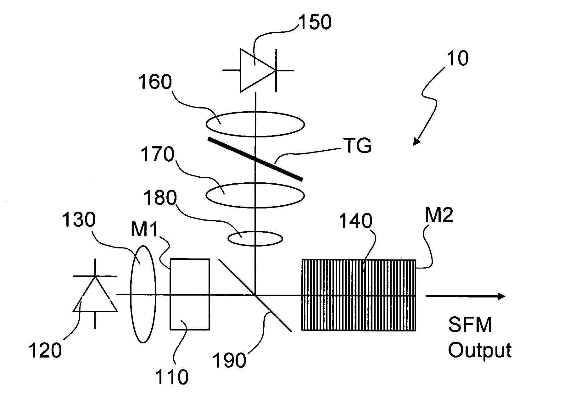
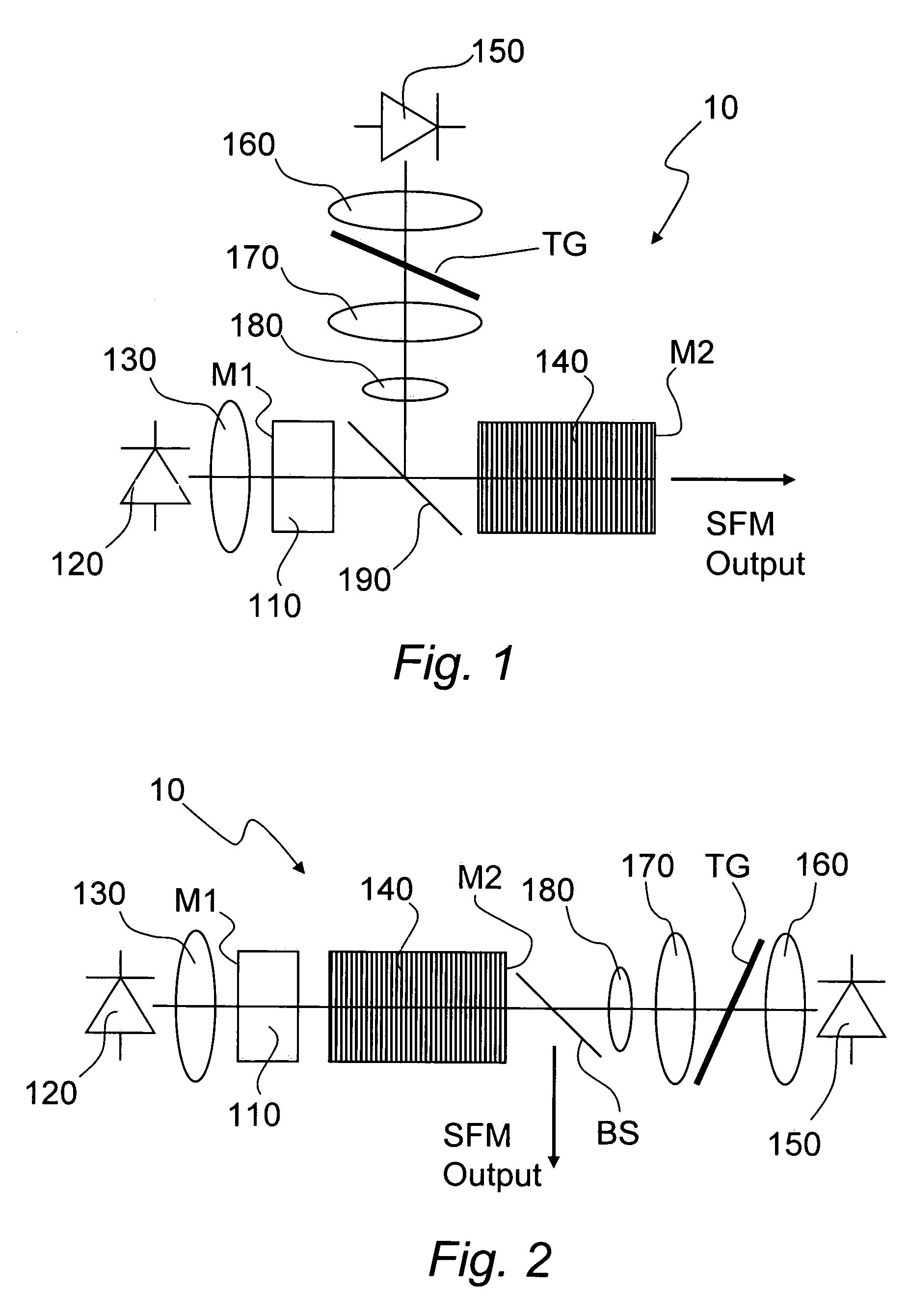
[0033]FIG. 1 shows schematically a first embodiment of a light source 10 according to the invention. The light source comprises an optically pumpable solid-state gain material 110 and a first diode laser (DL) 120 arranged to provide radiation for optical pumping to the gain material 110. In the optical path between the first DL 120 and the gain material 110, there is provided beam shaping optics 130 for transforming the beam output from the DL into a shape appropriate for pumping of the gain material 110. The gain material 110 is provided with a first cavity mirror M1 on the side facing the pumping DL 120. The light source further comprises an optically non-linear material 140 in the form of a periodically poled crystal. On the side facing away from the pumping DL 120, the periodically poled crystal is provided with a mirror constituting a second cavity mirror M2. Effec...


PUM


Abstract

A method and a device for generating visible coherent radiation is disclosed. The visible coherent radiation is generated by sum-frequency mixing of a first fundamental beam from a diode laser and a second fundamental beam from a diode-pumped solid-state laser. The mixing is performed by means of a quasi-phasematching element provided within the resonant cavity of the solid-state laser. The first fundamental beam is stabilized by providing feedback to the diode laser.

Description

TECHNICAL FIELD[0001]The present invention relates to a laser source incorporating sum-frequency mixing of two fundamental wavelengths.BACKGROUND OF THE INVENTION[0002]Low power, continuous-wave (CW) Ar+-ion lasers are widely used in applications like bioanalysis, graphics and semiconductor inspection. In many biotech applications, the 488 nm line from the Ar+-ion laser is employed. For this wavelength, particular chemistry has been developed and matched to fluorophores with relatively narrow absorption bands. During use, it is typically necessary to modulate the output from the laser in order, for example, to probe individual samples in an array. Such modulation has been effected primarily by means of acousto-optic modulators. It would thus be desirable to replace these bulky and rather inefficient Ar+-ion lasers with diode-pumped alternatives, particularly for generating said radiation at 488 nm or close thereto.[0003]In general, many applications require coherent light sources of...

Claims


Application Information

Patent Timeline
Patent Type & Authority Patents(United States)
IPC IPC(8): H01S3/10
CPCH01S3/109H01S3/005H01S3/0809H01S3/09415H01S3/1611H01S3/1673H01S3/2383
Inventor JOHANSSON, SANDRASPIEKERMANN, STEFANWANG, SHUNHUAPASISKEVICIUS, VALDASLAURELL, FREDRIKKARLSSON, HAKANEKVALL, KATRIN
Owner COBOLOT
Learn More