
Optical cable circuit failure point precision locating method

A technology for precise location and line faults, applied in transmission monitoring/testing/fault measurement systems, optical instrument testing, transmission systems, etc. The effect of shortened time

Inactive Publication Date: 2004-12-22
NANJING UNIV
View PDF0 Cites 31 Cited by
  • Summary
  • Abstract
  • Description
  • Claims
  • Application Information

AI Technical Summary

Problems solved by technology

However, it is necessary to accurately record the routing marker stone of the optical cable line during the construction and completion acceptance of the optical cable line, and use it as the completion data of the new construction. At the same time, it is powerless to locate the fault of the submarine optical cable

Method used


Image

  • Optical cable circuit failure point precision locating method
  • Optical cable circuit failure point precision locating method
  • Optical cable circuit failure point precision locating method

Examples


Embodiment Construction

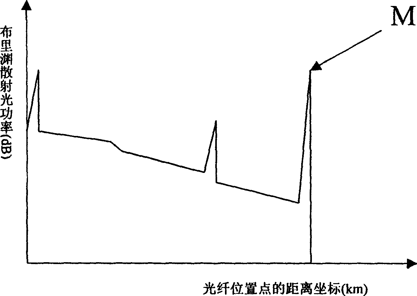
[0038] A method for accurately locating the fault point of an optical cable line according to the present invention, which adopts Brillouin optical time domain reflection technology, firstly, extracts the position information carried by the reflected light, roughly determines the position of the fault point of the optical cable, and simultaneously extracts the original location information of the optical cable line Strain information; secondly, make a preliminary estimate of the location of the fault point of the optical cable, use a temperature control box to heat the optical cable at a known position at an approximate position close to the fault point, and extract the position and strain information; then compare the initial measured value with the secondary The distance between the heating point of the optical cable and the fault point of the optical cable is determined according to the difference in the measured value; finally, the location of the fault point of the line is ...


PUM


Abstract

Using Brillouin reflectance technique in optical time domain adopted in the invention picks up strain information carried by Brillouin frequency drift caused by change of position information and temperature change carried in power of reflected light. Using method of combining absolute positioning with relative positioning makes successive approximation till exact location is determined finally. Comparing with prior art, the invention has features of omitting tedious calculation and additional data log, shortening time for finding out fault point of optical cable line so as to save cost. The method is general suitable method for positioning fault point applicable to optical cable line in position fixing direct burying type, aerial cable or duct optical cable.

Description

1. Technical field [0001] The invention relates to a method for locating the fault point of an optical cable line, specifically a method of using Brillouin Optical Time Domain Reflectometry (BOTDR), combining absolute positioning and relative positioning, and successively approaching to finally realize the fault of the optical cable precise positioning of points. 2. Background technology [0002] With the expansion of the construction scale of communication optical cable lines in my country and the aging phenomenon of existing optical cable lines over time, the possibility of failure of optical cable lines is also increasing. According to statistics, the line part accounts for 74.8% of the failures in the optical communication system, and the direct economic loss caused by the interruption of the optical cable line is 700-800 million yuan every year, which is amazing for the national economy and national defense communications. In the existing optical cable line maintenance...

Claims


Application Information

Patent Timeline
Patent Type & Authority Applications(China)
IPC IPC(8): G01M11/00H04B10/07
Inventor 张旭苹董玉明刘跃辉黄金源
Owner NANJING UNIV
Learn More