Eureka AIR delivers breakthrough ideas for toughest innovation challenges, trusted by R&D personnel around the world.

Wind turbine generator system

a generator system and wind turbine technology, applied in the direction of electric generator control, dynamo-electric converter control, instruments, etc., can solve the problems of difficult to follow the transient wind velocity change, the control of the pitch angle, and the inability to have a high response, so as to prevent the stop of the wind turbine and suppress the rotational velocity in the set range

Active Publication Date: 2007-09-11
HITACHI IND PROD LTD
View PDF19 Cites 46 Cited by
  • Summary
  • Abstract
  • Description
  • Claims
  • Application Information

AI Technical Summary

Benefits of technology

[0006]It is therefore an object of the present invention to provide a wind turbine generator system capable of controlling the wind turbine rotational velocity within an operation range even when the wind velocity suddenly changes so that the wind turbine can be continuously operated, thereby improving the wind turbine use ratio.
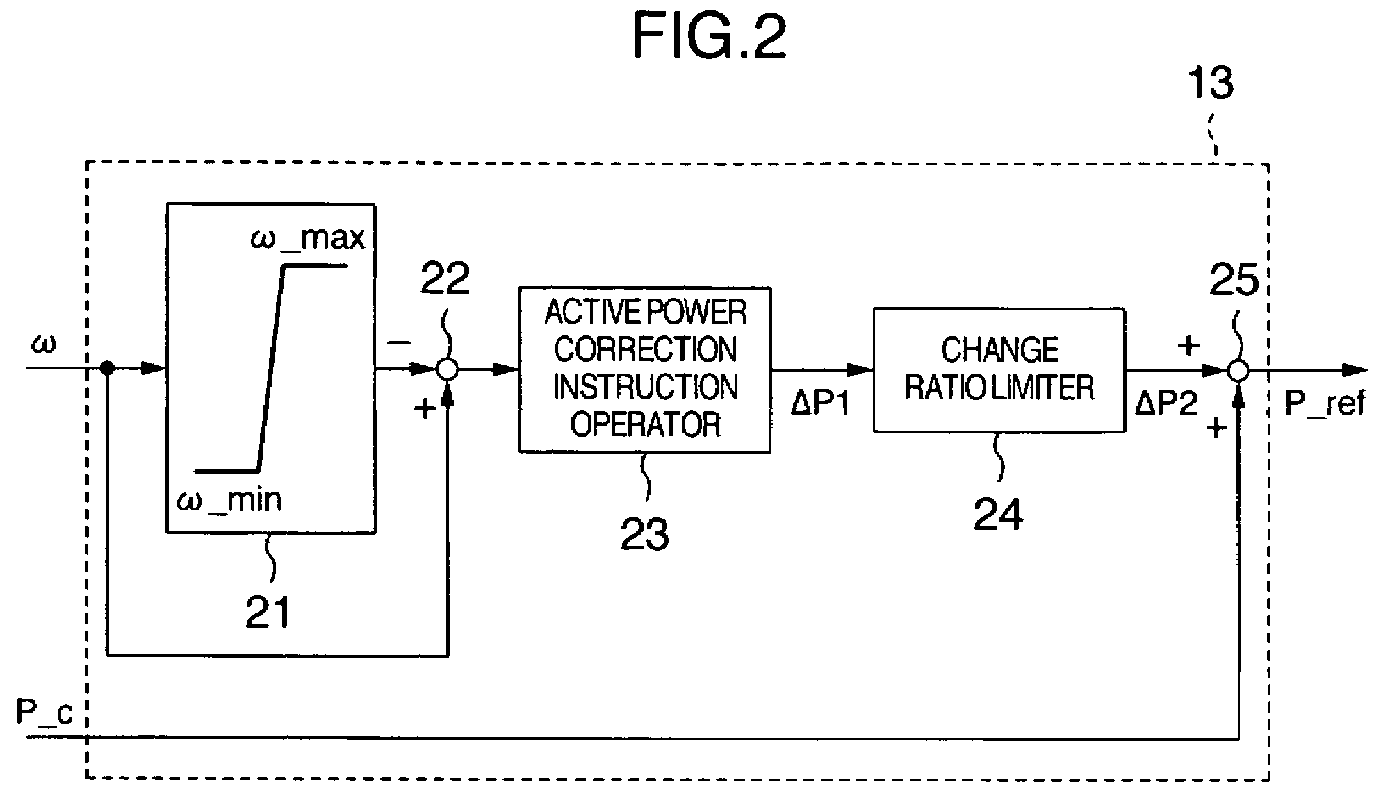
[0009]According to the present invention, it is possible to regulate the output of the wind turbine according to an instruction given from outside when the rotational velocity of the wind turbine is within a set range and when the rotational velocity of the wind turbine is out of the set range, the velocity is regulated so as to suppress the rotational velocity in the set range. Accordingly, when the wind velocity fluctuates, it is possible to prevent stop of the wind turbine.

Problems solved by technology

However, control of the pitch angle by driving the wind turbine blade according to the wind velocity includes mechanical operation and cannot have a high response.
When the power instruction given to the converter is adjusted according to the wind velocity, decision is normally made by the power curve based on the average wind velocity and it is difficult to follow the transient wind velocity change.

Method used


Image

  • Wind turbine generator system
  • Wind turbine generator system
  • Wind turbine generator system

Examples


embodiment 1

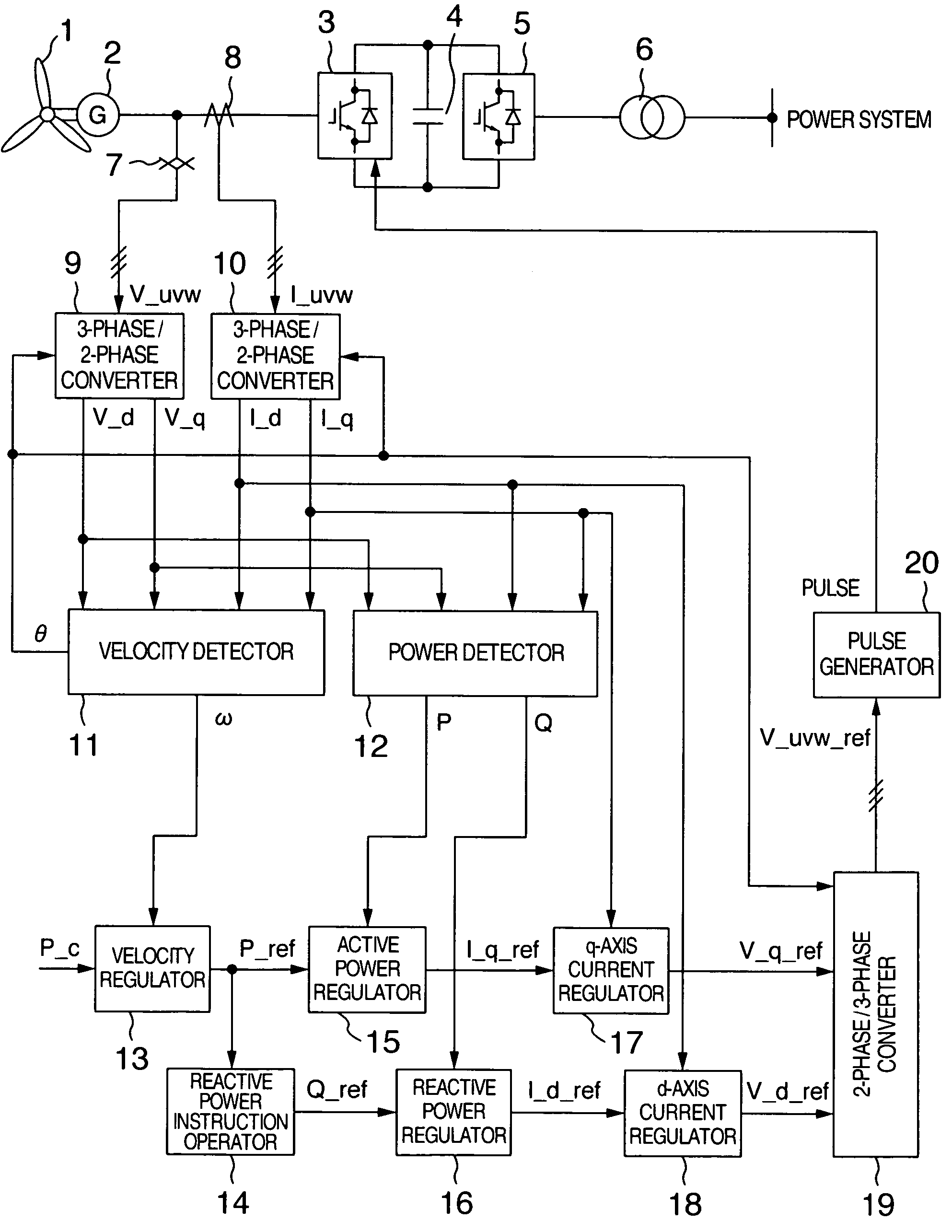
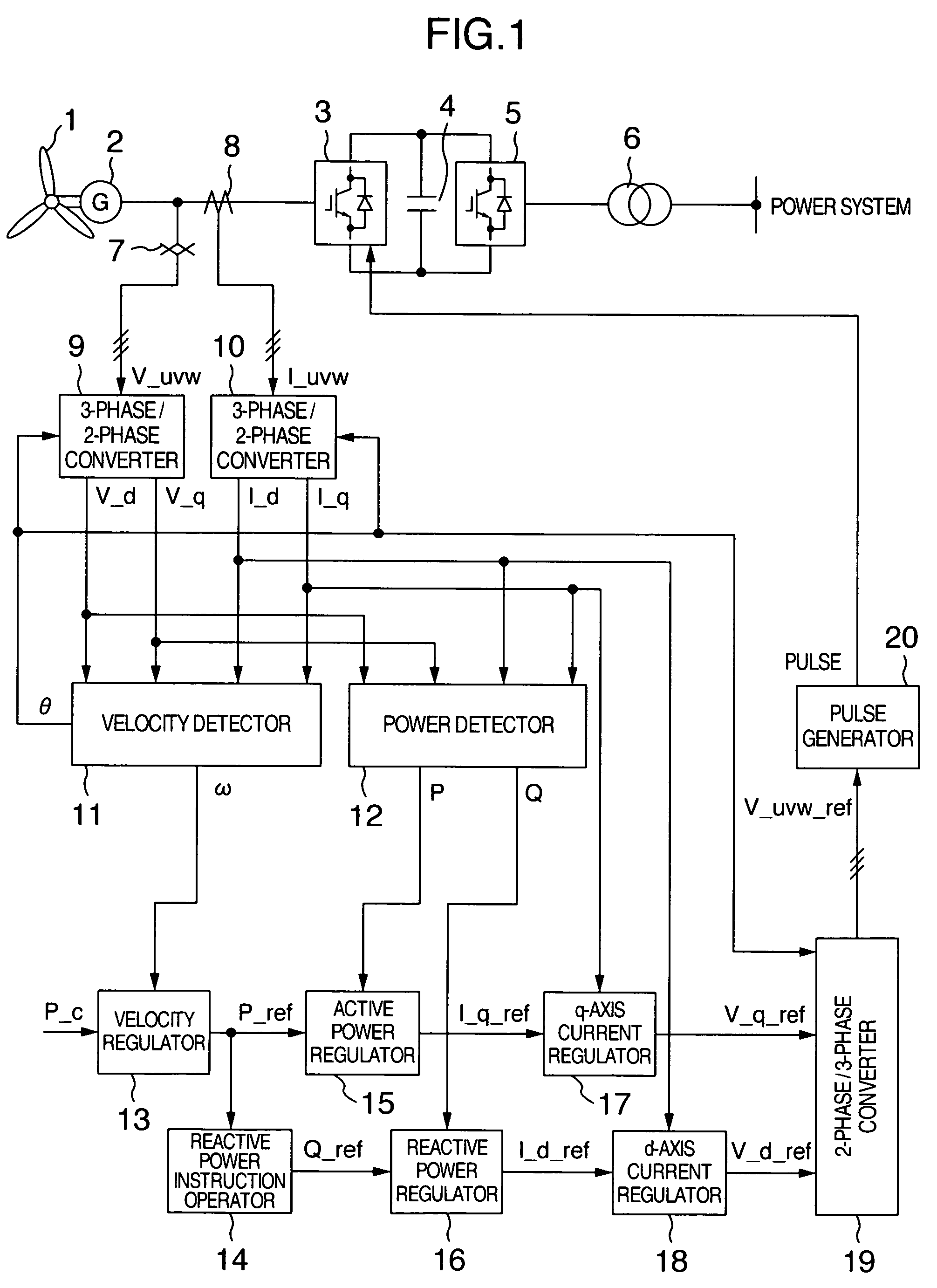
[0020]FIG. 1 shows the entire configuration of the present embodiment. As shown in FIG. 1, the synchronous generator 2 has a rotor connected to the shaft of the wind turbine 1. When the wind turbine 1 rotates according to the wind power based on the wind velocity, the synchronous generator 2 generates AC power of the variable frequency according to the rotational velocity of the wind turbine 1. The synchronous generator 2 has a stator connected to a converter 3. The AC power of variable frequency generated by the synchronous generator 2 is converted into DC power by the converter 3. The converter 3 is DC-connected to the converter5 via a DC capacitor 4. The converter 5 converts the DC power fed from the converter 3 into AC power of fixed frequency. The converter 5 is connected to a power system via a system linkage transformer 6 and supplies AC power of a fixed frequency to the power system.

[0021]Between the synchronous generator 2 and the converter 3, there are arranged a voltage d...

embodiment 2

[0037]FIG. 4 shows the entire configuration of the second embodiment using a doubly-fed generator. In FIG. 4, the rotor of the doubly-fed generator 26 is connected to the shaft of the wind turbine 1. When the wind turbine 1 rotates by the wind power in accordance with the wind velocity, the doubly-fed generator 26 connected to a power system by the stator supplies AC power matched with the system frequency to a power system. The rotor of the doubly-fed generator 26 is connected to a converter 27. The converter 27 AC-excites the rotor of the doubly-fed generator 26. The converter 27 is DC-connected to a converter 29 via a DC capacitor 28. The converter 29 supplies exciting power to the converter 27. The converter 29 is connected to the power system via a system linkage transformer 6.

[0038]Between the doubly-fed generator 26 and the converter 27, there are arranged a voltage detection sensor 30 and a current detection sensor 31. The voltage detection sensors detects a terminal voltage...

embodiment 3

[0051]FIG. 5 shows the entire configuration of the wind turbine generator system according to the present embodiment. The present embodiment uses a synchronous generator and the instruction given from outside serves as a torque instruction to the generator. The torque detector 39 shown in FIG. 5 detects torque T outputted from the synchronous generator 2 according to the signals V_d, V_q, I_d, I_q outputted from the 3-phase / 2-phase converters 9, 10 and the rotational velocity detection value ω detected by the velocity detector 11.

[0052]The velocity regulator 40 corrects the torque instruction T_c given to the synchronous generator 2 from outside according to the rotational velocity detection value ω detected by the velocity detector 11 and outputs the corrected torque instruction T_ref to the synchronous generator 2. The velocity regulator 40 has the same configuration as the velocity regulator 13 explained in the first and second embodiments.

[0053]The torque regulator 41 inputs the...


PUM


Abstract

A wind turbine generator system can regulate the rotational velocity of the wind turbine within an operation range even when the wind velocity suddenly changes and can perform continuous operation of the wind turbine. The wind turbine generator system includes a generator connected to the shaft of the wind turbine and a converter connected to the generator. When the rotational velocity of the wind turbine is within a predetermined range, power outputted from the generator is controlled so as to follow the instruction concerning the generator output given from the wind turbine to the converter. When the rotational velocity of the wind turbine is out of the predetermined range, the power outputted from the generator is controlled without following the instruction concerning generator output given from the wind turbine to the converter.

Description

BACKGROUND OF THE INVENTION[0001]The present invention relates to a wind turbine generator system, and in particular to a wind turbine generator system capable of continuous operation of a wind turbine by maintaining the rotational velocity of the wind turbine.[0002]Explanation will be given on the conventional wind turbine generator system. The wind turbine is connected to a generator. The wind turbine is rotated by wind power and the wind turbine drives the generator, so that the generator generates electricity. When using a synchronous generator as the generator, the stator of the generator is connected to a converter and AC power outputted from the generator is converted into DC power by the converter. Furthermore, the power is converted into AC power of a commercial frequency by an inverter and supplied to a power system. The converter regulates the output of the generator according to a power instruction given from outside. An example of the wind turbine generator system havin...

Claims


Application Information

Patent Timeline
Patent Type & Authority Patents(United States)
IPC IPC(8): F03D9/00H02H7/06H02P11/00H02P9/00H02P9/04
CPCH02P9/006F03D7/0272F03D7/028F03D7/042F03D9/002F03D9/003H02J3/386F05B2270/1016H02P2101/15F05B2270/327G09G2320/064Y02E10/723Y02E10/725Y02E10/763F05B2270/1033F03D9/25F03D9/255H02J2300/28H02J3/381Y02E10/76Y02E10/72H02J3/48
Inventor KIKUCHI, AKIRAICHINOSE, MASAYAFUTAMI, MOTOOMATSUTAKE, MITSUGUMIYAZAKI, KOUICHI
Owner HITACHI IND PROD LTD
Why Eureka
Eureka Blog
Learn More