
Systems and methods for load detection and correction in a digital amplifier

a digital amplifier and load detection technology, applied in single-ended push-pull amplifiers, electric devices, instruments, etc., can solve the problems of low performance applications, complex and costly applications to implement, and the solution is not widely accepted, so as to achieve less complex, easy to implement and maintain

Active Publication Date: 2007-08-21
INTERSIL INC
View PDF10 Cites 22 Cited by
  • Summary
  • Abstract
  • Description
  • Claims
  • Application Information

AI Technical Summary

Benefits of technology

The solution enables automatic adjustment of amplifier processing to maintain optimal frequency response across varying load impedances, reducing complexity and the need for manual adjustments, and improving scalability and flexibility compared to prior art systems.

Problems solved by technology

More particularly, these attempts utilized analog modulation schemes that resulted in low performance applications.
These applications were complex and costly to implement.
Consequently, these solutions were not widely accepted.
Prior art analog implementations of Class D technology have therefore been unable to displace legacy Class TAB amplifiers in mainstream amplifier applications.
These digital POM schemes, however, did little to offset the major barriers to integration of POM modulators into the total amplifier solution.
Class D technology has therefore continued to be unable to displace legacy Class TAB amplifiers in mainstream applications.
One of the problems with prior art systems and methods is that the quality and performance of the discrete output power switches and their associated drivers is unknown and varies as the performance and demand of the application change.
Another problem with prior art systems and methods is that the performance and quality characteristics of the remainder of the signal processing system vary with the applications in which they are used.
These point solutions are not flexible, scaleable or transportable across applications.
Yet another problem with prior art systems and methods is that their frequency responses vary with changes in the respective load impedances.

Method used


Image

  • Systems and methods for load detection and correction in a digital amplifier
  • Systems and methods for load detection and correction in a digital amplifier
  • Systems and methods for load detection and correction in a digital amplifier

Examples


Embodiment Construction

[0027]One or more embodiments of the invention are described below. It should be noted that these and any other embodiments described below are exemplary and are intended to be illustrative of the invention rather than limiting.

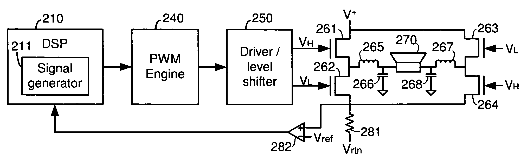
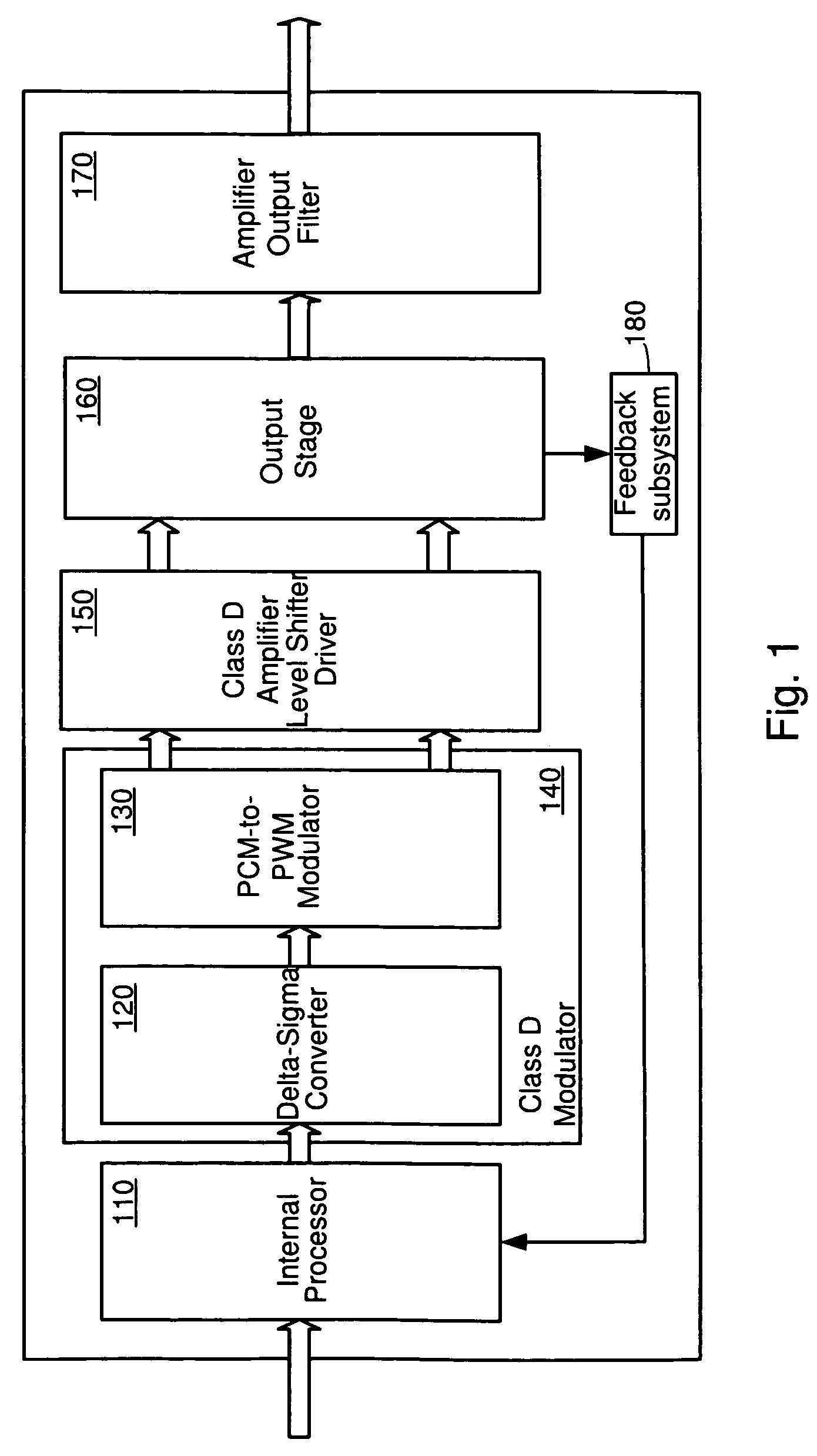
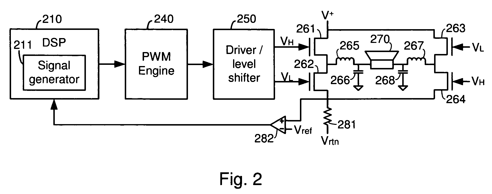
[0028]As described herein, various embodiments of the invention comprise systems and methods for detecting the impedance of an output load coupled to a digital amplifier and compensating for changes in the frequency response of the amplifier. One embodiment is implemented in a Class D pulse width modulated (POM) amplifier. A mechanism is provided for determining the impedance of a speaker that is coupled to the output of the amplifier. The processing of the digital audio signal is then adjusted if necessary to optimize the frequency response of the amplifier for the specific impedance of the speaker.

[0029]In this embodiment, a digital test signal (e.g., a sine wave) is generated. This test signal is processed by the amplifier to produce a corresponding analog...


PUM


Abstract

Systems and methods for detecting the impedance of an output load coupled to a digital amplifier and compensating for changes in the response of the amplifier. One embodiment of the invention is implemented in a Class D pulse width modulated (PWM) amplifier. In this embodiment, a digital PCM test signal is generated. This test signal is processed by the amplifier to produce a corresponding analog audio output signal that is used to drive a speaker. A sense resistor placed in series with the speaker is used to generate a test voltage that is compared to a reference voltage. When the test voltage reaches the reference voltage, the current through the sense resistor (hence the speaker) is at a known level, so the value of the digital test signal is noted. The impedance of the speaker is then determined from the test signal value and the speaker current.

Description

RELATED APPLICATIONS[0001]This application claims priority to U.S. Patent application Ser. No. 10 / 805,741, entitled “Systems And Methods For Automatically Adjusting Channel Timing,” by Taylor, et al., filed Mar. 22, 2004, which claims priority to: U.S. Provisional Patent Application No. 60 / 456,421, entitled “Output Device Switch Timing Correction,” by Taylor, et al., filed Mar. 21, 2003; U.S. Provisional Patent Application No. 60 / 456,414, entitled “Adaptive Anti-Clipping Protection,” by Taylor, et al., filed Mar. 21, 2003; U.S. Provisional Patent Application No. 60 / 456,430, entitled “Frequency Response Correction,” by Taylor, et al., filed Mar. 21, 2003; U.S. Provisional Patent Application No. 60 / 456,429, entitled “High-Efficiency, High-Performance Sample Rate Converter,” by Anderson, et al., filed Mar. 21, 2003; U.S. Provisional Patent Application No. 60 / 456,422, entitled “Output Filter, Phase / Timing Correction,” by Taylor, et al., filed Mar. 21, 2003; U.S. Provisional Patent Appli...

Claims


Application Information

Patent Timeline
Patent Type & Authority Patents(United States)
IPC IPC(8): H03F3/38G01R19/00H03F1/52
CPCH03F1/523H03F3/2173H03F3/2175H03F2200/331H03F2200/426
Inventor HAND, LARRY E.TAYLOR, WILSON E.
Owner INTERSIL INC
Learn More