Dynamic microphone

Inactive Publication Date: 2013-03-21
AUDIO-TECHNICA
View PDF1 Cites 4 Cited by
  • Summary
  • Abstract
  • Description
  • Claims
  • Application Information

AI Technical Summary

Benefits of technology

The present invention is about a dynamic microphone which solves problems with demagnetization and increases sensitivity. The microphone uses a first permanent magnet and a second permanent magnet, which are polarized in the same sense. This results in an increase in magnetic flux and sensitivity. The use of alnico and neodymium magnets provides sound quality improvement and sensitivity enhancement, respectively. Overall, the technical effects of the dynamic microphone include increased sensitivity, reduced demagnetization, and improved sound quality.

Problems solved by technology

Further, in view of restrictions on a gap volume in the magnetic gap G and output impedance, it is hard to increase the length of the voice coil 13.
Furthermore, since the velocity of the voice coil 13 depends on the design of the acoustic mechanical vibration of the microphone unit, it is undesirable to increase the velocity taking into consideration the general directional frequency response.
However, in the case of combining the above-mentioned magnets, a problem arises in that the permanent magnet 2 made of alnico is likely to be demagnetized by the second permanent magnet 31 made of neodymium.

Method used


Image

  • Dynamic microphone
  • Dynamic microphone
  • Dynamic microphone

Examples


Embodiment Construction

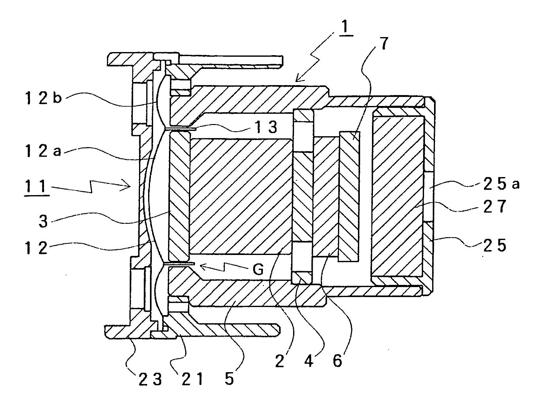
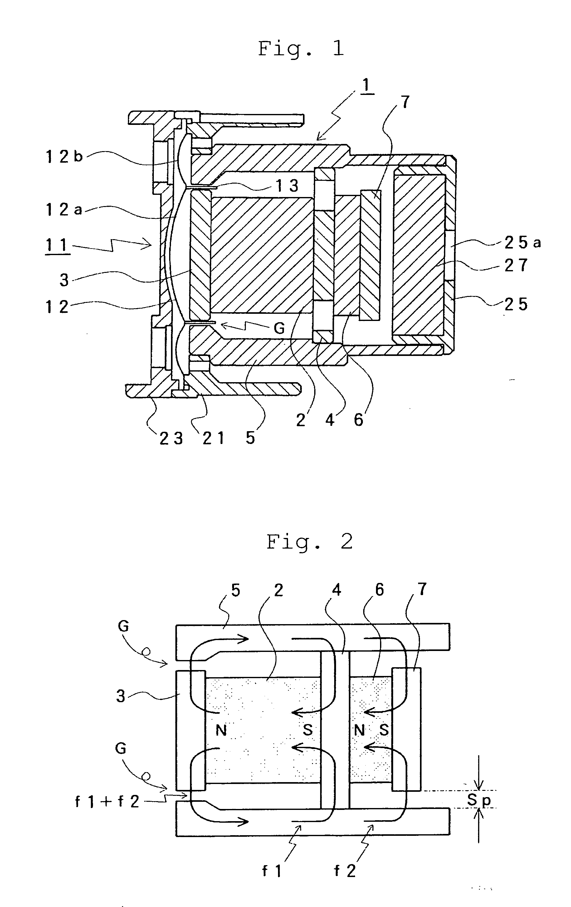
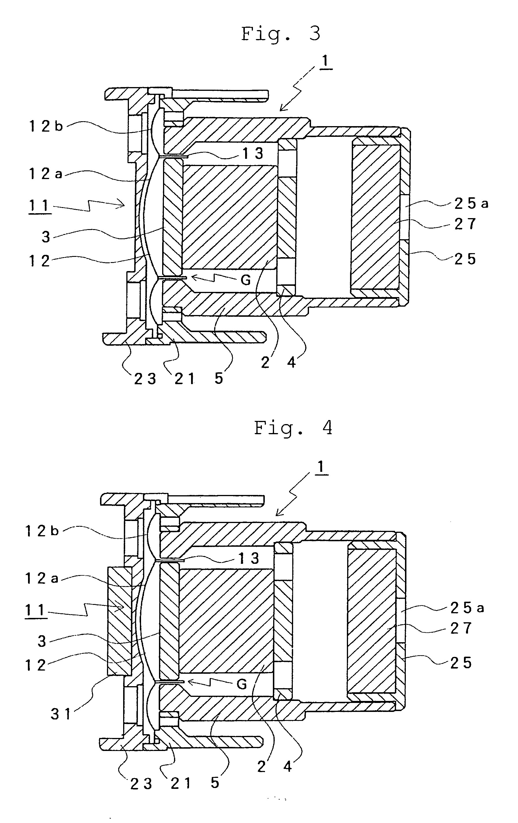
[0037]A dynamic microphone in accordance with the present invention will be described with reference to a sectional view showing an internal structure illustrated in FIG. 1 and a schematic diagram of a magnetic circuit shown in FIG. 2. It should be noted that, in FIG. 1, parts which function similarly to those illustrated in FIG. 3 above are denoted by the same reference signs. Accordingly, the description of these parts will not be repeated herein.

[0038]In addition to the structure shown in and already described with reference to FIG. 3, a first permanent magnet 2 is in contact with one side of a tail yoke 4 and a second permanent magnet 6 is disposed on the other side (the opposite side) of the tail yoke in the dynamic microphone in accordance with the present invention shown in FIG. 1.

[0039]In other words, a first magnetic pole of the second permanent magnet 6 is disposed in contact with the tail yoke 4, a second polar piece 7 is further disposed in contact with a second magnetic...


PUM


Abstract

A microphone includes a polar piece contacting with a first magnetic pole of a first permanent magnet, a yoke body annularly arranged around the polar piece through a magnetic gap G with a predetermined width, a magnetic circuit unit including a tail yoke connected to the yoke body and contacting with a second magnetic pole of the first permanent magnet, and a diaphragm unit provided with a voice coil arranged to vibrate in the magnetic gap. The second magnetic pole of the first permanent magnet contacts with one side of the tail yoke, a first magnetic pole of the second permanent magnet is disposed to contact with other side of the tail yoke, a magnetic path is produced between the second magnetic pole of the second permanent magnet and the yoke body, and the first permanent magnet and the second permanent magnet are polarized in the same sense.

Description

BACKGROUND OF THE INVENTION[0001]1. Field of the Invention[0002]The present invention relates to a dynamic microphone and more particularly to a dynamic microphone in which a flux density in a magnetic gap where a voice coil is disposed is increased to improve sensitivity.[0003]2. Description of the Related Art[0004]A dynamic microphone is arranged such that a voice coil attached to a diaphragm is disposed in a magnetic gap formed in a magnetic circuit so that vibration of the diaphragm generates electric current in the voice coil, and therefore called an electro-dynamic microphone as well.[0005]FIG. 3 shows in section an example of a conventional dynamic microphone. Reference numeral 1 indicates a magnetic circuit unit. A cylindrical permanent magnet (magnet) 2 is provided in the center of this magnetic circuit unit 1. A disk-shaped polar piece 3 is arranged in contact with one magnetic pole (for example, north(N) pole) of this permanent magnet 2. Further, a disk-shaped tail yoke 4...

Claims


Application Information

Patent Timeline
IPC IPC(8): H04R3/00
CPCH04R9/08H04R9/025
Inventor AKINO, HIROSHI
Owner AUDIO-TECHNICA
Why Eureka
Try Eureka