
Rare gas-halogen excimer lasers with baffles

a gashalogen excimer laser and laser technology, applied in lasers, laser details, active medium materials, etc., can solve the problems of sputtered electrode material contamination of laser gases and optics, unable to achieve a practical excimer laser, etc., to achieve the effect of reducing the flow rate of laser gas, extending the lifetime of the excimer laser, and reducing the formation of contaminants

Active Publication Date: 2007-08-14
MELA SCIENCES
View PDF4 Cites 24 Cited by
  • Summary
  • Abstract
  • Description
  • Claims
  • Application Information

AI Technical Summary

Benefits of technology

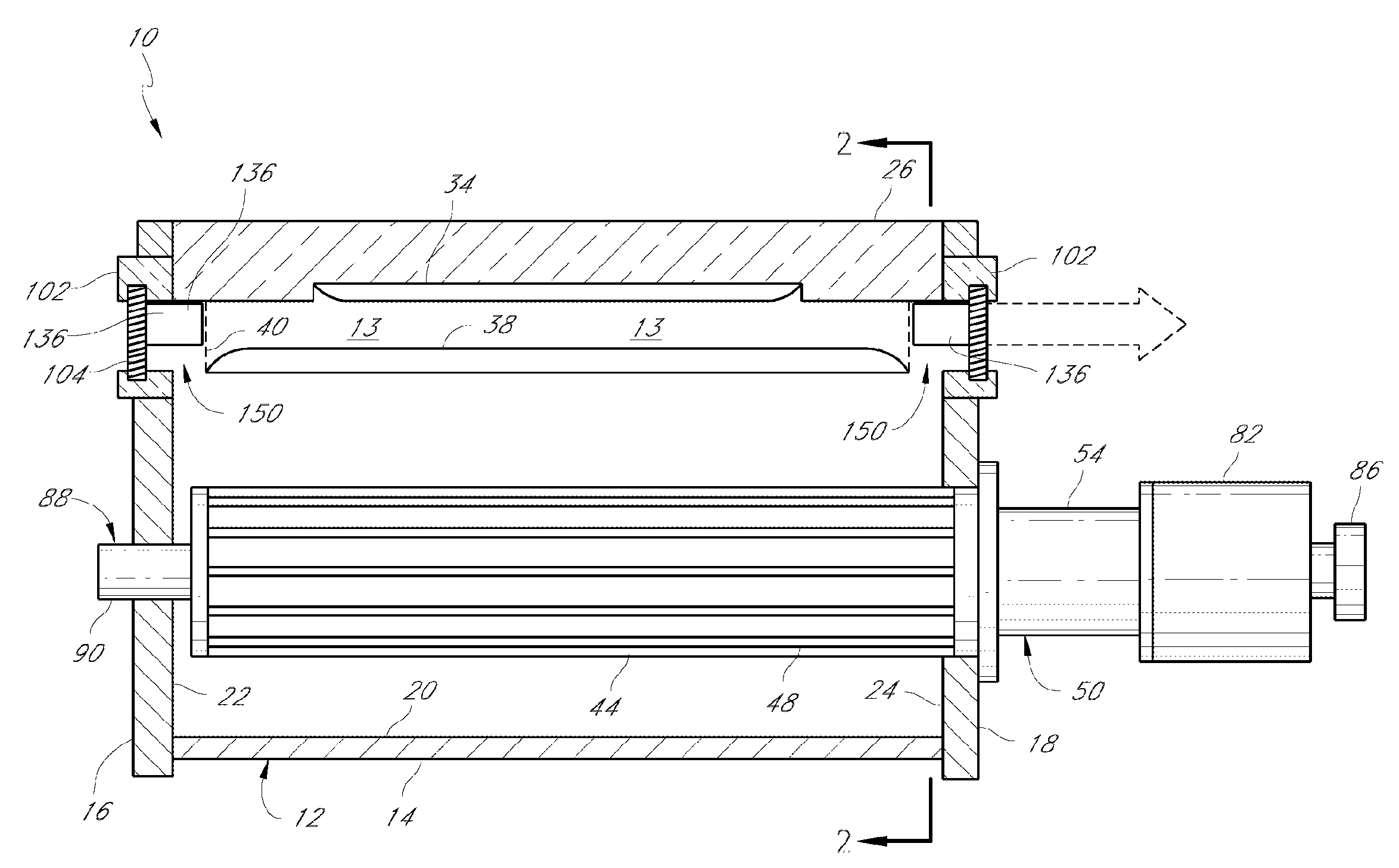
[0009]One aspect of the invention comprises an excimer laser comprising a chamber for containing laser gases, a pair of electrodes, and an optical resonant cavity. The pair of electrodes energizes the gases in a region between the electrodes so as to produce light emission from the gases. The optical resonant cavity comprises a plurality of mirrors that produce a laser beam from the light emitted from the gases, the laser beam propagating in the chamber. The laser further comprises a window on the chamber for egress of the laser beam from the chamber and a fan for circulating the laser gases in the chamber. The laser additionally comprises a baffle comprising an elongated hollow member within the chamber proximal to the window. The elongate hollow member has a hollow passageway for passage of the laser beam. The elongated hollow member also has a proximal opening and a distal opening. The passageway extends from the proximal opening to the distal opening. The elongate hollow member is disposed within the chamber such that the laser beam enters the proximal opening, propagates through the hollow passageway, and exits the distal opening and through the window. The baffle reduces contamination of the window. Preferably, a substantially greater flow of the laser gases flows around the baffle than through the hollow passageway in the elongated hollow member.
[0010]Another aspect of the invention comprises an excimer laser comprising a chamber for containing laser gases, a pair of electrodes, and an optical resonant cavity. The pair of electrodes produces an electronic discharge. The electrodes are disposed with respect to each other in the chamber so as to form an active region therebetween. Light is emitted from the active region when a voltage is applied to the electrodes. The active region coincides with at least a portion of the optical resonant cavity. The light emitted from the active region resonating within the optical resonant cavity forms a laser beam. The laser further comprises a window on the chamber for egress of the laser beam from the chamber. The laser beam propagates through a portion of the window coincident with the laser beam. A fan circulates the laser gases in the chamber and through the active region. A baffle restricts the flow of gas across the portion of the window coincident with the laser beam.
[0011]Another aspect of the invention comprises a method of extending the lifetime of an excimer laser. This laser comprises a pressure vessel for containing laser gases, an active region for producing a laser beam in the pressure vessel, and at least one optical surface in the pressure vessel, a portion of which is coincident with the laser beam. The method comprises reducing the rate of flow of laser gases across the portion of the optical surface coincident with the laser beam to reduce formation of contaminants on the portion of the optical surface coincident with the laser beam.
[0012]Another aspect of the invention comprises an excimer laser comprising a pressure vessel of the type in which a halogen gas is contained, first and second electrodes, first and second reflective elements, and a fan for circulating the gases. The first and second electrodes create a laser discharge between the electrodes. The first and second reflective elements form a laser cavity in the pressure vessel. The laser discharge produces a laser beam in the laser cavity. The first and second optical surfaces are oppositely situated in the pressure vessel. The laser beam propagates between these first and second optical surfaces. The excimer laser further comprises flow control surfaces within the pressure vessel to direct the flow of gases circulating within the pressure vessel away from portions of the optical surfaces on which the laser beam is incident such that the rate at which particulates are deposited on such surfaces where the laser beam is incident is substantially reduced. The portions of the pressure vessel, first and second electrodes, fan, and flow control surfaces that are in contact with the halogen gas are fabricated substantially of materials that react with the halogen gas to form stable reaction products having vapor pressures of less than about 10−6 torr, at normal operating temperatures, such that the lifetime of the excimer laser is increased by not adding or creating any substantial quantity of laser contamination. Contamination is therefore substantially reduced.
[0013]Another aspect of the invention comprises an excimer laser comprising a pressure vessel for containing a halogen gas, first and second electrodes, first and second optical elements, and first and second flow-redirecting surfaces. The first and second electrodes are located within the pressure vessel. The first and second electrodes are separated such that a voltage applied between the first and second electrodes produces a gas discharge that emits light. The first and second optical elements are located at opposite ends of the pressure vessel. The first and second optical elements are disposed with respect to the separation between the first and second electrodes to receive the emitted light. The first and second flow-redirecting surfaces are located adjacent to the first and second optical elements, respectively. The flow-redirecting surfaces reduce the rate at which gases in the pressure vessel flow adjacent the optical component where the optical component receives the emitted light. These flow-redirecting surfaces may comprise baffles at optical windows on the pressure vessel.

Problems solved by technology

This potential success has remained to a large extent unfulfilled because of numerous problems that limit the period of time during which excimer lasers will operate without requiring substantial maintenance or experiencing performance difficulties.
One of the obstacles to achieving a practical excimer laser is the challenge of obtaining a homogeneous volumetric discharge between the longitudinally extending lasing electrodes.
Such inhomogeneous arcing between the electrodes causes the eventual destruction of the electrodes as well as contamination of the laser gases and optics with sputtered electrode material.
These additional components within the laser cavity, however, may be potential sources of contamination of the laser gases.
Another difficulty with conventional excimer lasers is that contamination of the laser gases or the optics in the pressure vessel necessitates that major maintenance and / or disassembly of the laser be frequently undertaken such as, for example, in the case where the windows need to be replaced.
At typical pulse rates of between about 10 and 500 pulses per second, the operating time between such maintenance procedures or disassembly is on the order of hours, rendering such excimer lasers impractical for many, if not most, applications.
In addition, because the toxic and corrosive gases used in excimer lasers must be carefully handled during disassembly of the laser and subsequent reassembly, such procedures are complicated and potentially hazardous.

Method used


Image

  • Rare gas-halogen excimer lasers with baffles
  • Rare gas-halogen excimer lasers with baffles
  • Rare gas-halogen excimer lasers with baffles

Examples


Embodiment Construction

[0020]The following description of a preferred embodiment of the present invention is presented for purposes of illustration, and should not be taken in a limiting sense.

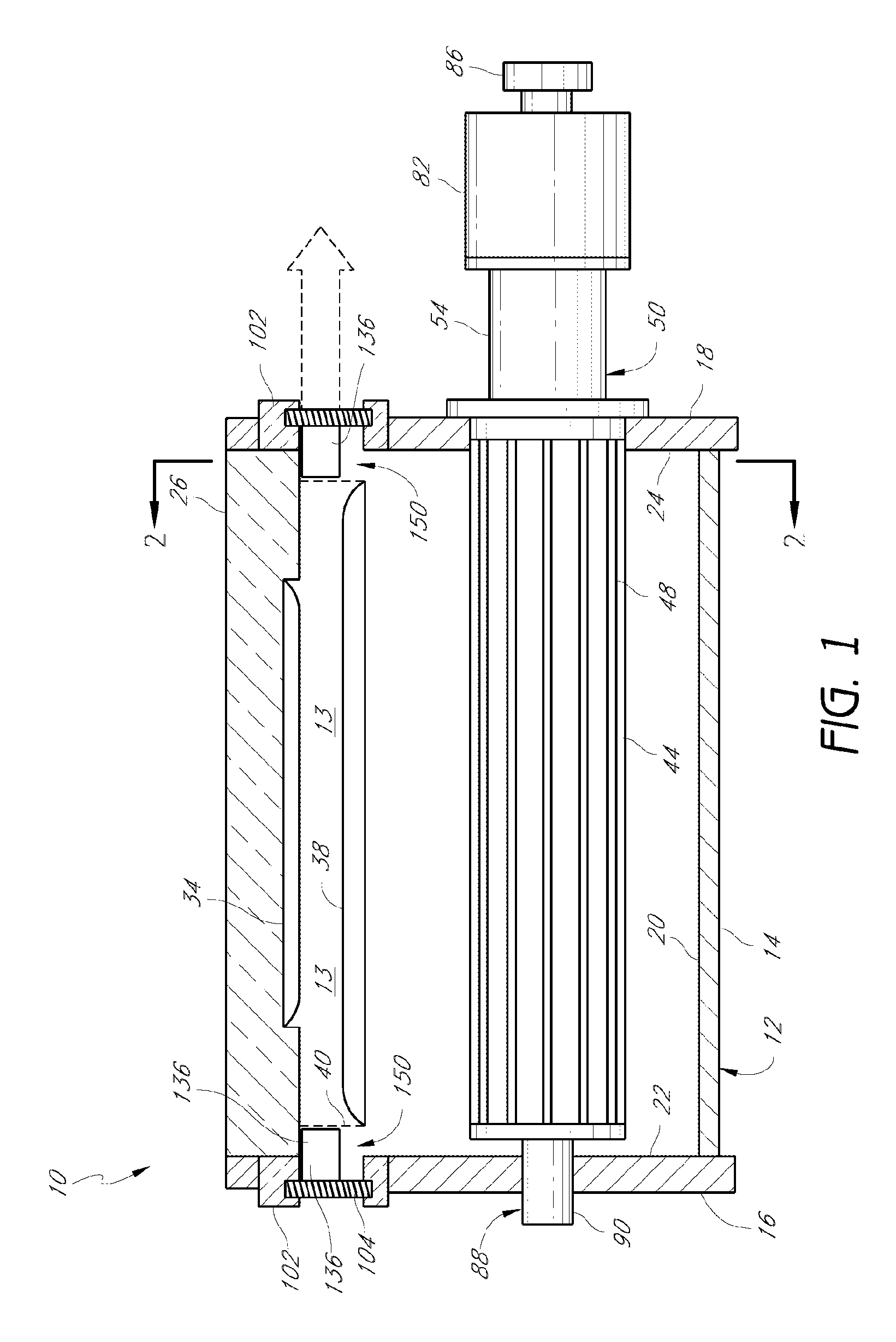
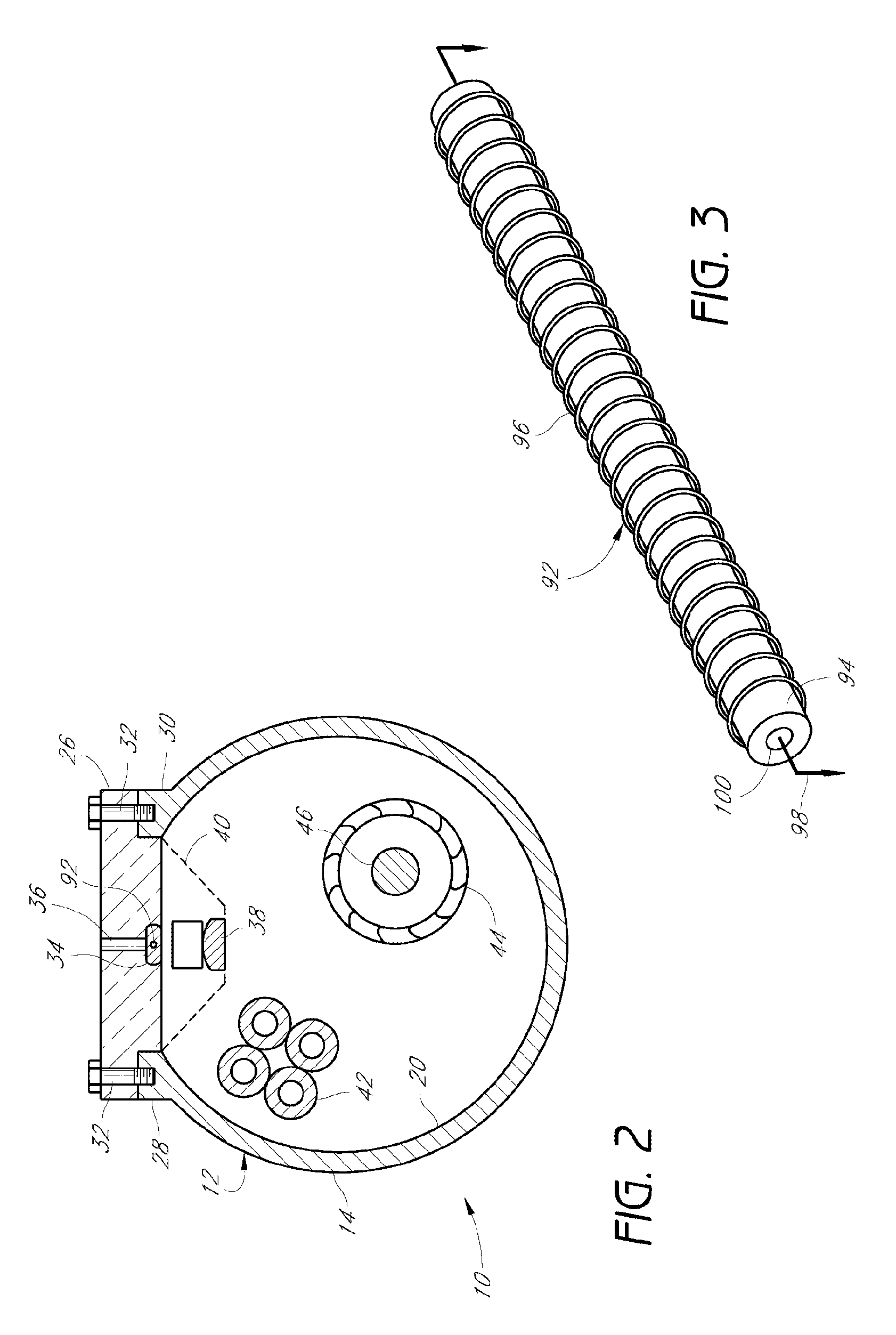
[0021]Cross-sectional views of an exemplary excimer laser 10 is shown in FIGS. 1 and 2. The excimer laser 10 comprises a pressure vessel 12 for containing rare gas and halide gas or gas containing halide. The laser 10 is equipped with electrodes 34, 38 for exciting a discharge in a region 13 between oppositely facing surfaces of the electrodes. This region 13 is referred to herein as the active region of the laser 10. The laser 10 includes reflective optics that form a laser cavity encompassing at least a portion of the active region 13. These reflective optics may comprise a pair of mirrored or substantially reflective optical elements. One of these reflective optical elements is at least partially transmissive for egress of the light beam from the laser cavity to provide laser output. Light generated within the ac...


PUM


Abstract

An excimer laser comprises a gas chamber, electrodes for creating rare gas / halide molecules that disassociate and produce optical emission, and reflective surfaces that form an optical resonant cavity. The excimer laser further comprises flow control surfaces that define gas flow paths and that control the flow of gas within the chamber. Preferably such flow control surfaces direct the gases away from the laser optics. More preferably, the flow control surfaces shield the path of the laser beam, at least in the proximity of the laser optics, from contaminants in the gases. Less contaminants yields less contamination of the laser optics. As a result, the laser device becomes more reliable and useful over longer periods of time. In addition, the laser gases are preferably exposed only to compatible materials that react with the laser gases to produce stable reaction products having a low vapor pressure, so as to reduce contamination of the gases and the optics. High-purity nickel is preferred for components that are electrically conductive, and high-purity alumina is preferred for components that are non-electrically conductive. Preferably, incompatible materials are not used.

Description

BACKGROUND OF THE INVENTION[0001]1. Field of the Invention[0002]The present invention relates to an improvement in rare gas-halogen excimer lasers, and in particular, to an improvement for increasing the operational lifetime, reliability, efficiency, and / or performance of such lasers.[0003]2. Description of the Related Art[0004]An excimer laser uses a rare gas such as krypton, xenon, argon or neon, and a halide gas or a gas containing a halide, for example F2 or HCl, as the !active components. The active components and possibly other gases are contained in a pressure vessel provided with longitudinally extending lasing electrodes for inducing a transverse electrical discharge in the gases. The discharge causes the formation of excited rare gas-halide molecules whose disassociation results in the emission of ultraviolet photons constituting the laser light. The laser further comprises mirrors or reflective surfaces that form an optical cavity that establish an optical resonance condi...

Claims


Application Information

Patent Timeline
Patent Type & Authority Patents(United States)
IPC IPC(8): H01S3/22H01S3/03H01S3/034H01S3/036H01S3/225
CPCH01S3/036H01S3/225
Inventor LEVATTER, JEFFREY I.
Owner MELA SCIENCES
Learn More