Portable nuclear detector

a detector and portable technology, applied in the field of nuclear detection, can solve the problems of unsatisfactory output, physical disruption, post-incident cleanup, psychological trauma to the workforce and populace, etc., and achieve the effect of fast, robust and inexpensive techniqu

Inactive Publication Date: 2007-07-24
ARMY US GOVERNMENT AS REPRESENTED BY SECY OF THE
View PDF19 Cites 8 Cited by
  • Summary
  • Abstract
  • Description
  • Claims
  • Application Information

AI Technical Summary

Benefits of technology

[0009]Accordingly, it is an object of the present invention to provide a fast, robust, and inexpensive technique for the detection and classification of nuclear material.
[0011]It is still another object of the present invention to provide a nuclear material detector that possesses an excellent spectral resolution without a burdensome analysis process.
[0012]Yet another object of the present invention is to provide a nuclear material detector capable of localizing the presence of nuclear materials with high spatial directivity.

Problems solved by technology

They can cause physical disruption, interruption of economic activity, post-incident cleanup, and psychological trauma to a workforce and populace.
This method is not immune to noise or clutter, thereby providing unsatisfactory output.
Mechanically, existing radioactive material detectors are large in size and extremely fragile, making them unsuitable for remote sensing and detecting applications, for example within the mass transit system of a major metropolitan area.
Furthermore, extant systems require a long acquisition time for isotope identification and classification, and do not provide spatial directivity.
This is undesirable from a rapid response or rapid reaction standpoint.

Method used


Image

  • Portable nuclear detector
  • Portable nuclear detector
  • Portable nuclear detector

Examples


Embodiment Construction

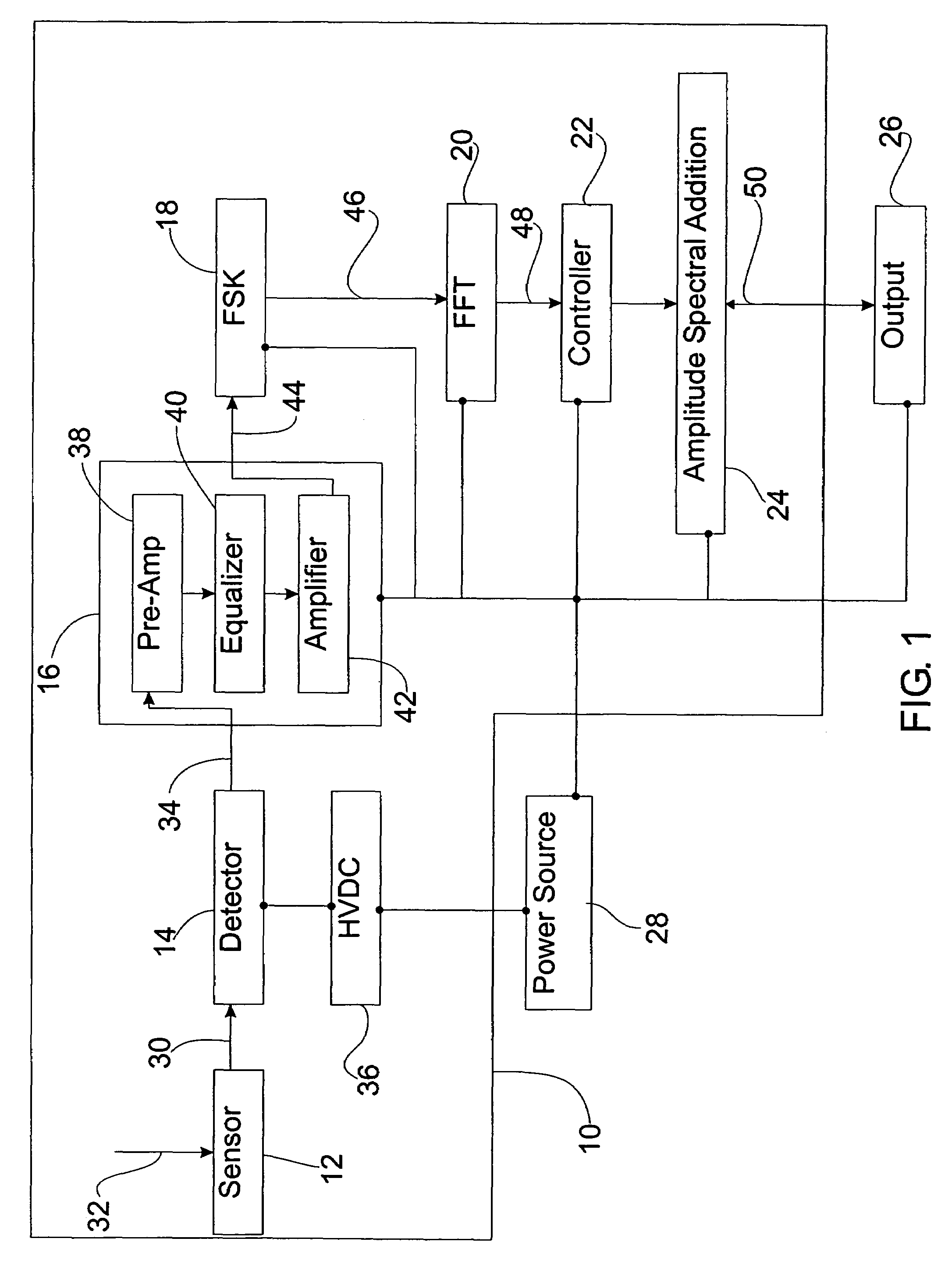
[0018]Referring now to the drawings, and especially to FIG. 1, there is shown a block diagram of a nuclear material detector 10 according to the present invention. Nuclear material detector 10 generally includes a scintillating fiber radiation sensor 12, a light detector 14 optically coupled to scintillating fiber radiation sensor 12, a conditioning circuit 16 in operable communication with light detector 14, a frequency shift keying (FSK) circuit 18 in operable communication with conditioning circuit 16, a fast Fourier transform (FFT) circuit 20 in operable communication with FSK circuit 18, an electronic controller 22 in operable communication with FFT circuit 20, and an amplitude spectral addition circuit 24 in operable communication with electronic controller 22. An output device 26 in bi-directional operable communication with amplitude spectral addition circuit 24 is also provided to provide output information from nuclear material detector 10. In embodiments, a power source 2...


PUM


Abstract

A portable nuclear material detector generally includes a scintillating fiber radiation sensor, a light detector, a conditioning circuit, a frequency shift keying (FSK) circuit, a fast Fourier transform (FFT) circuit, an electronic controller, an amplitude spectral addition circuit, and an output device. A high voltage direct current (HVDC) source is provided to excite the light detector, while a separate power supply may be provided to power the remaining components. Portability is facilitated by locating the components of the detector within a handheld-sized housing. When bombarded by gamma particles, the radiation sensor emits light, which is detected by the light detector and converted into electrical signals. These electrical signals are then conditioned and converted to spectral lines. The frequency of a give spectral line is associated with a particular radioactive isotope, while the cumulative amplitude of all spectral lines having a common frequency is indicative of the strength and location of the isotope. All or part of this information (identity, strength, direction, and distance) may be provided on the output device.

Description

STATEMENT REGARDING FEDERALLY SPONSORED RESEARCH OR DEVELOPMENT[0001]The invention described herein may be manufactured and used by or for the United States Government for governmental purposes without the payment of any royalties thereon.CROSS-REFERENCES TO RELATED APPLICATIONS[0002]Not Applicable.BACKGROUND OF THE INVENTION[0003]1. Field of the Invention[0004]The present invention relates generally to nuclear detection, and, more particularly, to a portable gamma radiation detector.[0005]2. Background Description[0006]Radioactive nuclear materials can be used to contaminate water supplies, business centers, government facilities, or transportation networks. They can cause physical disruption, interruption of economic activity, post-incident cleanup, and psychological trauma to a workforce and populace. In fact, the possibility of a radiological terrorist attack, often referred to as a “dirty bomb,” is a fear that drives many anti-terrorism preparedness efforts. Accordingly, detect...

Claims


Application Information

Patent Timeline
Patent Type & Authority Patents(United States)
IPC IPC(8): G01T1/167
CPCG01T1/201
Inventor CASTELLANE, RAYMOND M.DURST, BARTLEY P.AHMAD, FALIH H.
Owner ARMY US GOVERNMENT AS REPRESENTED BY SECY OF THE
Why Eureka
Try Eureka