Method and arrangement for producing radiation

a radiation and radiation technology, applied in the field of radiation production methods, can solve the problems of unstable or weak radiation of plasma, no solution suggested to the problem, and energy pulses that might not hit the target optimally, etc., and achieve the effect of positioning fluctuations in the targ

Inactive Publication Date: 2007-07-03
JETTEC AB
View PDF11 Cites 55 Cited by
  • Summary
  • Abstract
  • Description
  • Claims
  • Application Information

AI Technical Summary

Benefits of technology

[0009]Therefore, it is an object of the present invention to provide an improved method for producing X-ray or EUV radiation by energy beam produced plasma emission, wherein the detrimental effects of these positional fluctuations in the target are eliminated, or at least considerably reduced.
[0010]In general, it is an object of the present invention to improve pulse-to-pulse and long-term stability of position, flux and spatial distribution of the emitted radiation from a plasma produced by directing an energy pulse such as a laser pulse onto a target.

Problems solved by technology

However, no solution to the said problem is suggested.
The reason for this has been identified as that the plasma-producing beam simply does not “hit” the target optimally, thus intermittently producing an unstable or weakly radiating plasma.
Moreover, there are other reasons that the energy pulse might not hit the target optimally.
This leads to a positional uncertainty regarding the target position relative to the energy pulse, and hence to fluctuations in the produced radiation.
Also, the target might in fact be a frozen jet that has broken up into fragments, causing a similar positional uncertainty.

Method used


Image

  • Method and arrangement for producing radiation
  • Method and arrangement for producing radiation
  • Method and arrangement for producing radiation

Examples


Embodiment Construction

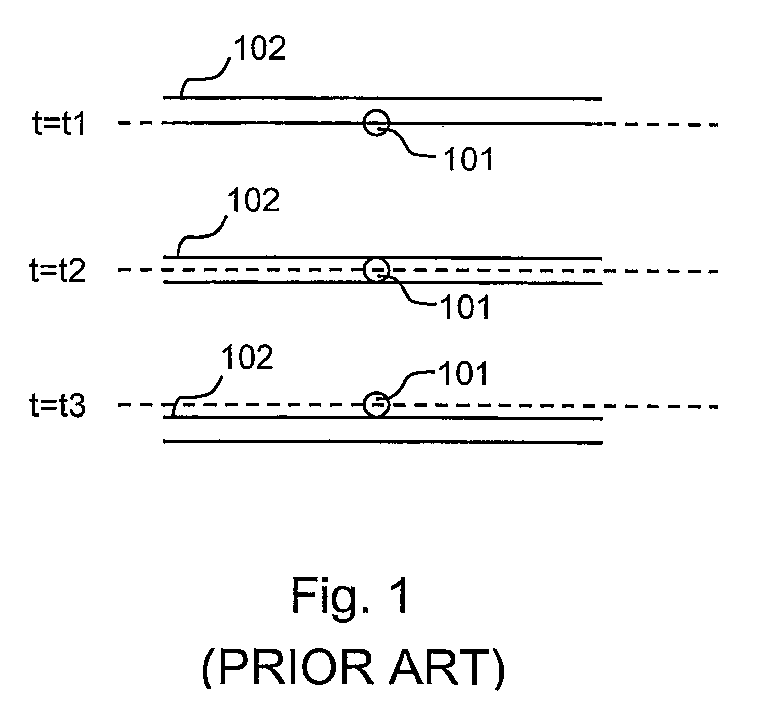
[0032]Referring now to FIG. 1 of the accompanying drawings, the stability problem encountered in the prior art will be briefly discussed. Typically, in the field of laser produced plasma emission, the laser focus 101 has an ideally fixed position in space. However, even in good laser systems, there might be beam pointing stability issues that cause, or add to, relative positional fluctuations between the target 102 and the laser beam 101. Any perturbation of the target position or the laser beam will therefore cause the laser pulses to partially or entirely miss the target 102. As schematically shown in FIG. 1, the laser pulse 101 is ideally centered at the same position (shown in the figure by a broken line). At time t1 the position of the target may have moved such that the: laser pulse 101 only partially hits the target 102; at time t2 the position of the target 102 may actually be appropriate; and at time t3 the position of the target 102 may be such that the laser pulse 101 mis...


PUM


Abstract

A method of producing a radiating plasma with an increased flux stability and uniformity is disclosed. The method comprises the steps of generating a primary target by urging a liquid under pressure through a nozzle; directing an energy pre-pulse onto the primary target to generate a secondary target in the form of a gas or plasma cloud; allowing the thus formed secondary target to expand for a predetermined period of time; and directing a main energy pulse onto the secondary target when the predetermined period of time has elapsed in order to produce a plasma radiating X-ray or EUV radiation. The pre-pulse has a beam waist size that is larger, in at least one dimension, than the corresponding dimension of the primary target.

Description

[0001]This is a national phase filing under 35 U.S.C. § 371 of International Application No. PCT / EP03 / 04984, filed May 13, 2003, that designates the United States of America. The benefit is claimed under 35 U.S.C. § 119(a)–(d) of Swedish Application No. 02076898.2, filed May 13, 2002, and under 35 U.S.C. § 119(e) of U.S. Provisional Application No. 60 / 398,014, filed Jul. 24, 2002.TECHNICAL FIELD[0002]The present invention relates to a method for producing X-ray or extreme ultraviolet (EUV) radiation. In particular, the present invention relates to improvements in flux stability and uniformity in connection with energy beam produced plasmas.BACKGROUND OF THE INVENTION[0003]EUV and X-ray sources of high intensity are applied in many fields, for instance surface physics, materials testing, crystal analysis, atomic physics, medical diagnostics, lithography and microscopy. Conventional X-ray sources, in which an electron beam is brought to impinge on an anode, generate a relatively low X...

Claims


Application Information

Patent Timeline
Patent Type & Authority Patents(United States)
IPC IPC(8): H05G2/00G21K1/00G21G4/00G21K5/02G21K5/08G21K7/00H01J35/00H01L21/027H05H1/00H05H1/24
CPCH05G2/003H05G2/008
Inventor BERGLUND, MAGNUSHANSSON, BJORNHEMBERG, OSCARHERTZ, HANSRYMELL, LARS
Owner JETTEC AB
Why Eureka
Try Eureka