
Method and device for refining a glass melt using negative pressure

Inactive Publication Date: 2007-06-19
SCHOTT AG
View PDF8 Cites 61 Cited by
  • Summary
  • Abstract
  • Description
  • Claims
  • Application Information

AI Technical Summary

Benefits of technology

[0015]In a particularly preferred embodiment of the device, the components comprise individual sections, in particular pipe sections, which are connected to one another by means of a flange connection or a screw connection. Pipe sections can be produced and processed further easily and inexpensively from refractory metals or their alloys. The connections between the pipe sections can be made gas-tight in a particularly simple way by means of cutting edges. An additional sealing action is achieved if the pipe sections which have been connected to one another are annealed, preferably at temperatures of over 1000° C., during which step the contact locations are welded or sintered together.
[0016]The cutting edge seal is a static connection which is free of sealing material. It is used here to connect rotationally symmetrical pipe sections. To increase the pressure, at in each case one of the pipe pairs which are to be connected the sealing surface (planar bearing surface) is reduced in size in such a manner that concentrically encircling cutting edges which are V-shaped in cross section are formed. When the connecting locations are clamped together, the pressure on the cutting edges is increased to such an extent that, if necessary, the material can flow.
[0020]Furthermore, the heating of the components may also be effected by induction or by direct flow of high-frequency alternating current in the component. Heating by means of direct flow of current in the glass melt using a central stick electrode and the component as a counterelectrode is also advantageous in particular if the glass melt has a sufficient electrical conductivity.

Problems solved by technology

For example, ceramic refractory materials, when in contact with a glass melt, are subject to considerable wear and increased corrosion compared to platinum and its alloys.
This entails firstly short plant operating times and a high outlay on maintenance and repair and secondly a high potential for the formation of glass defects (formation of cords, inclusions, bubbles in particular in the downpipe).
Furthermore, heating presents problems for glass melts which cannot be heated directly by electrical means or can only be heated in this way with difficulty.
With regard to the formation of glass defects, it is preferable to use platinum or platinum alloys, but the capital costs which this incurs are very high.

Method used


Image

  • Method and device for refining a glass melt using negative pressure
  • Method and device for refining a glass melt using negative pressure
  • Method and device for refining a glass melt using negative pressure

Examples


Embodiment Construction

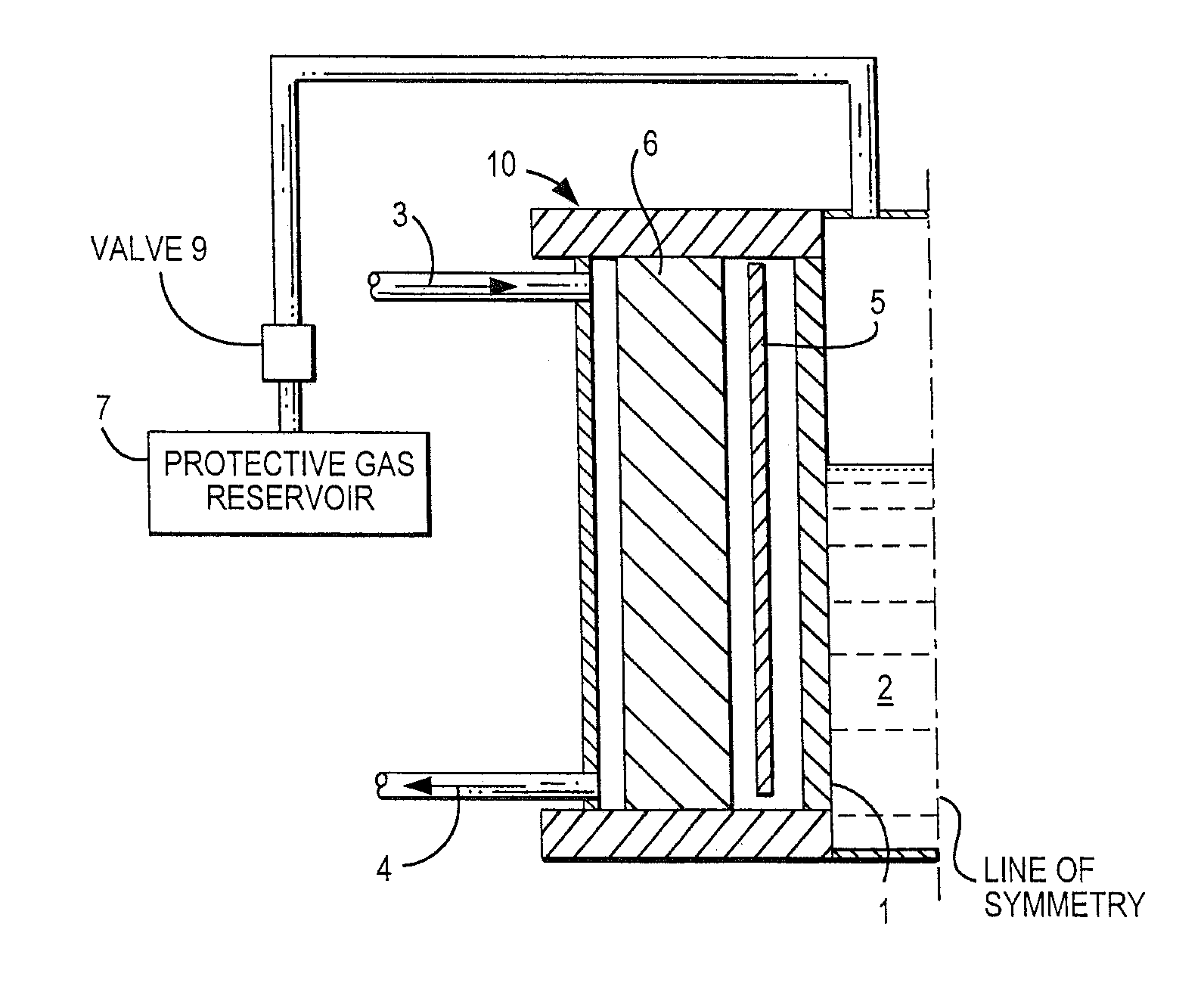
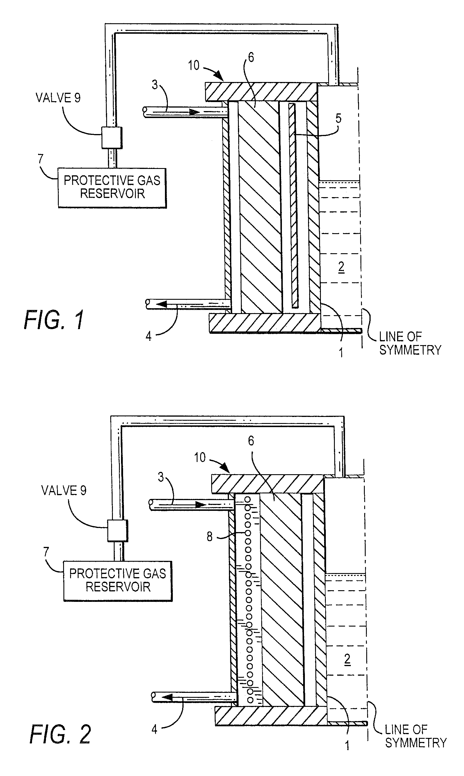
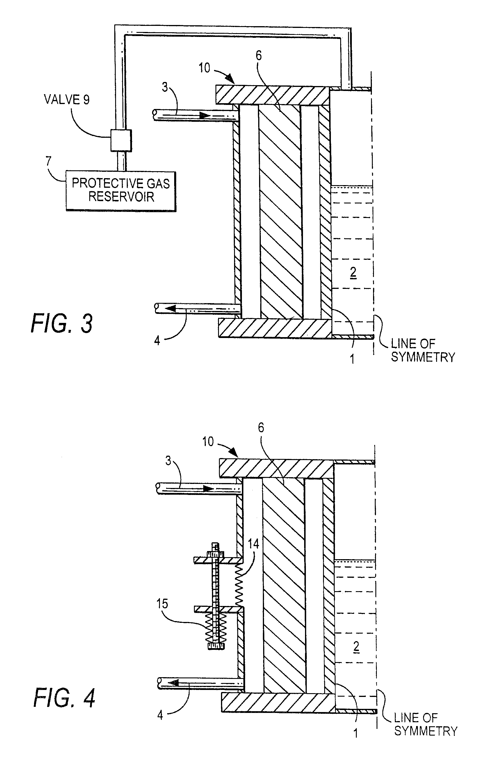
[0027]FIG. 1 shows part of a device according to the invention for the reduced-pressure refining of a glass melt using a reduced-pressure apparatus in which the glass melt (2) is fed to a refining bank via a riser and is discharged again from the refining bank via a downpipe, a reduced pressure being generated by means of the glass flow in the refining bank and the riser and / or the downpipe and / or the refining bank having at least one component (1) made from at least one refractory metal and / or from a refractory metal alloy as glass-contact material.

[0028]The component (1), which is of tubular design and is preferably made from molybdenum or tungsten or a corresponding alloy, is surrounded by a housing (10) (e.g. made from steel, aluminum or plastic). The feed (3) and discharge (4) for the protective gas or forming gas are also located in the housing.

[0029]On the side remote from the glass melt, the component (1) is protected from oxidation by flushing with a protective gas or formi...


PUM

PropertyMeasurementUnit
Temperatureaaaaaaaaaa
Pressureaaaaaaaaaa
Frequencyaaaaaaaaaa

Abstract

The apparatus for reduced-pressure refining of a glass melt includes a refining bank formed so that a reduced pressure is generated by a glass flow in it. The refining bank has a component, which is made from a refractory metal or refractory alloy acting as glass-contact material. The refractory metal or alloy contains molybdenum, tungsten, tantalum, and / or hafnium. The device of the present invention includes a protective gas reservoir for a protective gas and an automatically operating valve connecting the reservoir with the refining bank so that an inner side of the component that would otherwise be exposed when a pressure rise or a falling glass melt column occurs is protected from oxidation by the protective gas. A process for using the device during refining of the glass melt is also part of the invention.

Description

CROSS-REFERENCE[0001]This is the U.S. National Stage of PCT / EP 01 / 12197, filed Oct. 23, 2001, which, in turn, claims the benefit of priority of invention under 35 U.S.C. 119 (a) and 35 U.S.C. 365 (b) based on DE 100 54 881.4 filed Nov. 6, 2000 in Germany and based on DE 101 28 674.0 filed Jun. 13, 2001 in Germany.BACKGROUND OF THE INVENTION[0002]The invention relates to a process and device for the reduced-pressure refining of a glass melt using a reduced-pressure apparatus, in which the glass melt is fed to a refining bank via a riser and is discharged again from the refining bank via a downpipe, a reduced pressure being generated by means of the glass flow in the refining bank.[0003]The refining of the glass melt, i.e. the removal of gas bubbles from the glass melt, is used to eliminate bubbles. With small crucible melts, the rise of the gas bubbles out of the glass melt has already been accelerated by means of the application of a reduced pressure above the glass melt.[0004]Devic...

Claims


Application Information

Patent Timeline
IPC IPC(8): C03B5/225C03B5/167C03B5/43
CPCC03B5/1672C03B5/2252
Inventor KARETTA, FRANKWITTE, JOERGDUCH, KLAUS-DIETERGOHLKE, DIRKMUENCH, WOLFGANGJAKWAY, ALLENEICHHOLZ, RAINERLENTES, FRANK-THOMAS
Owner SCHOTT AG
Learn More