Shaft for fluid dynamic bearing, fluid dynamic bearing device, and method of manufacturing the shaft

a technology of fluid dynamic bearing and shaft, which is applied in the direction of sliding contact bearings, manufacturing tools, mechanical equipment, etc., can solve the problems of high cost, difficult to increase machining accuracy, and failure to generate the desired fluid dynamic between the shaft and the bearing, etc., and achieves low cost and high accuracy.

Inactive Publication Date: 2007-06-05
NHK SPRING CO LTD
View PDF17 Cites 5 Cited by
  • Summary
  • Abstract
  • Description
  • Claims
  • Application Information

AI Technical Summary

Benefits of technology

[0012]It is an object of the present invention to provide a shaft for a fluid dynamic bearing, which has the rotation stability to control a half whirl and decrease the rotation frequency at start of contact between a shaft and a bearing in a low rotation frequency range, a fluid dynamic bearing device having the shaft, and a method of manufacturing the shaft for a fluid dynamic bearing with a high accuracy at a low cost.
[0013]A shaft for a fluid dynamic bearing according to the present invention has a plurality of grooves arranged in and around the external circumference, a surface of the grooves and external circumference with a uniform roughness, and machined marks on the surface aligned in the circumferential direction. The grooves are at least partially continued to minimize deflection of the rotation shaft for a fluid dynamic bearing. The grooves are formed parallel to the axis of rotation to stabilize the distribution along the axial direction of the force acting in the radial direction of the rotation shaft. The grooves are formed so that the phase in the rotating direction centering on the axis of rotation changes along the center of the shaft, to control the flow direction of the fluid in the grooves. The grooves are formed so that the external circumference is changed like a sine wave in the radial direction along the circumference, to prevent deviation of the rotation shaft stability to the rotating direction, and to smooth the contact between the shaft and a bearing.
[0023]An odd number is desirable from a viewpoint of rotation stability. However, if the odd number is larger than 15, the shape of the external circumference is close to a circle, the generated fluid dynamic is dispersed, and a desired effect cannot be obtained. Though the lower limit value is 3, the rotation may be unstable in the high-speed side with an odd number 3. In a range of 5–9, the machining stability (reproducibility) is good, the yield is improved, and excellent characteristics can be obtained.

Problems solved by technology

In these machining processes, it is difficult to increase the machining accuracy above than a certain level.
Formation of a separation layer may cause a failure to generate a desired fluid dynamic between the shaft and the bearing.
Thus, it is difficult to decrease the cost of machining the shaft.

Method used


Image

  • Shaft for fluid dynamic bearing, fluid dynamic bearing device, and method of manufacturing the shaft
  • Shaft for fluid dynamic bearing, fluid dynamic bearing device, and method of manufacturing the shaft
  • Shaft for fluid dynamic bearing, fluid dynamic bearing device, and method of manufacturing the shaft

Examples


Embodiment Construction

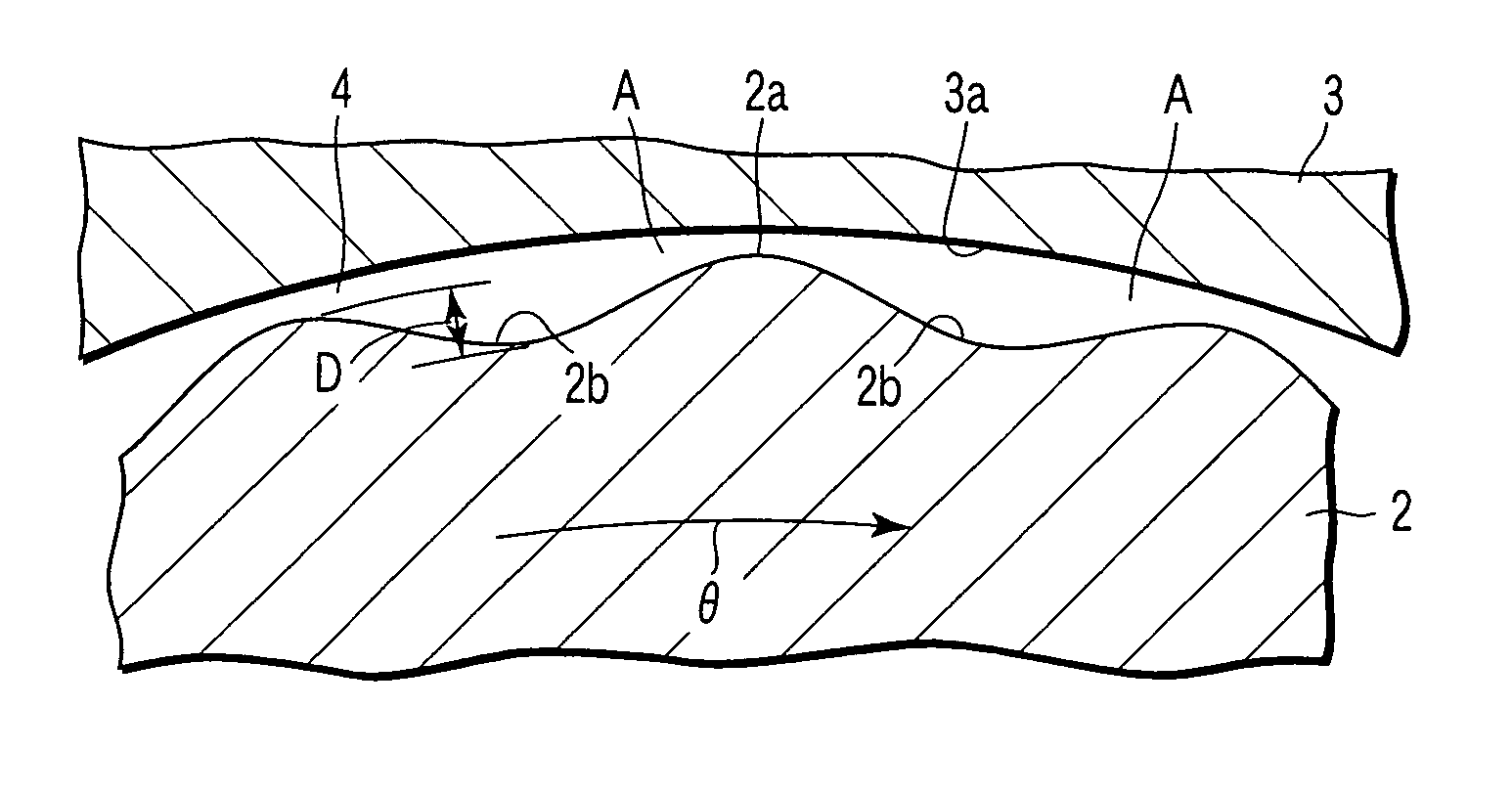
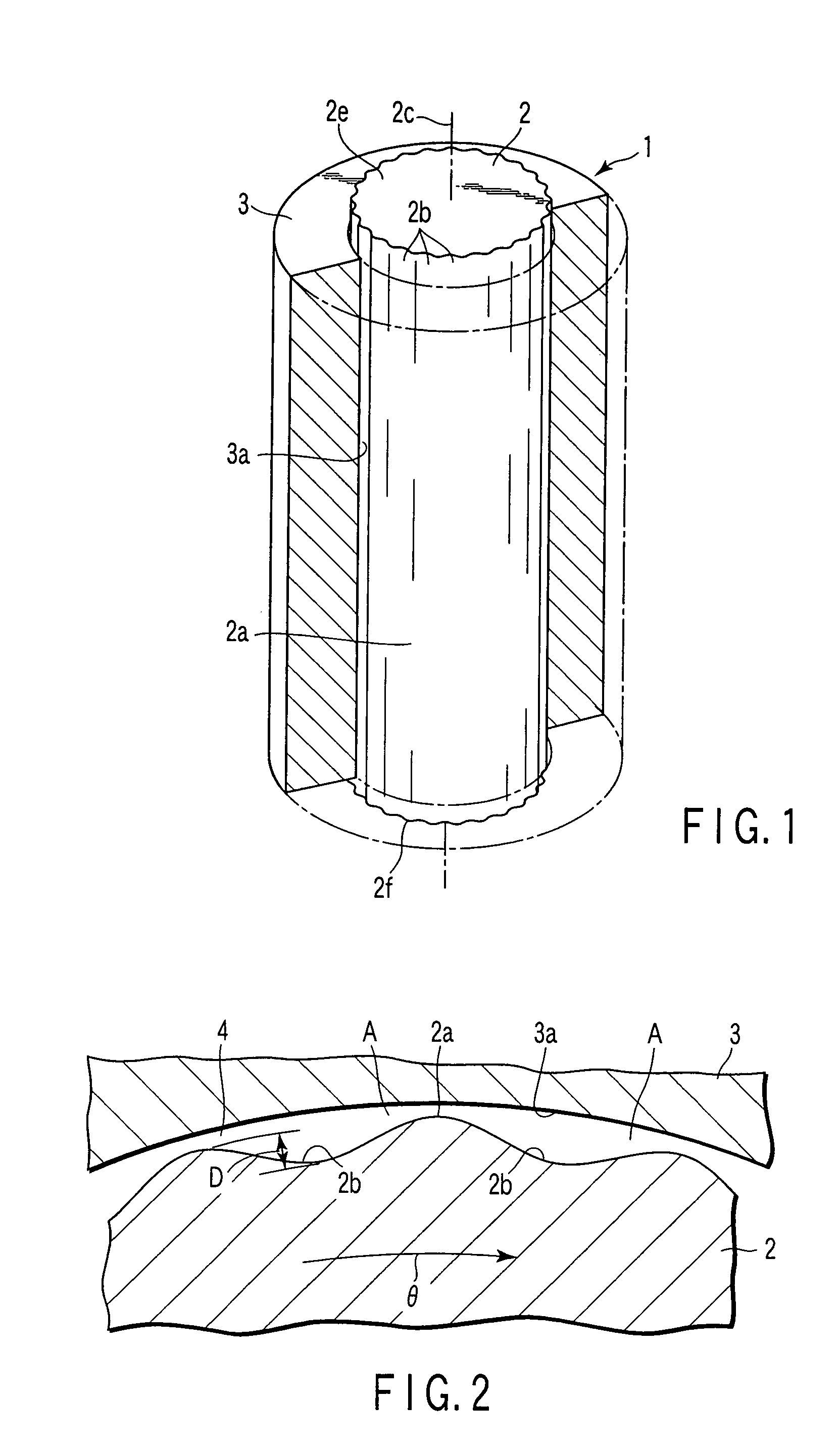
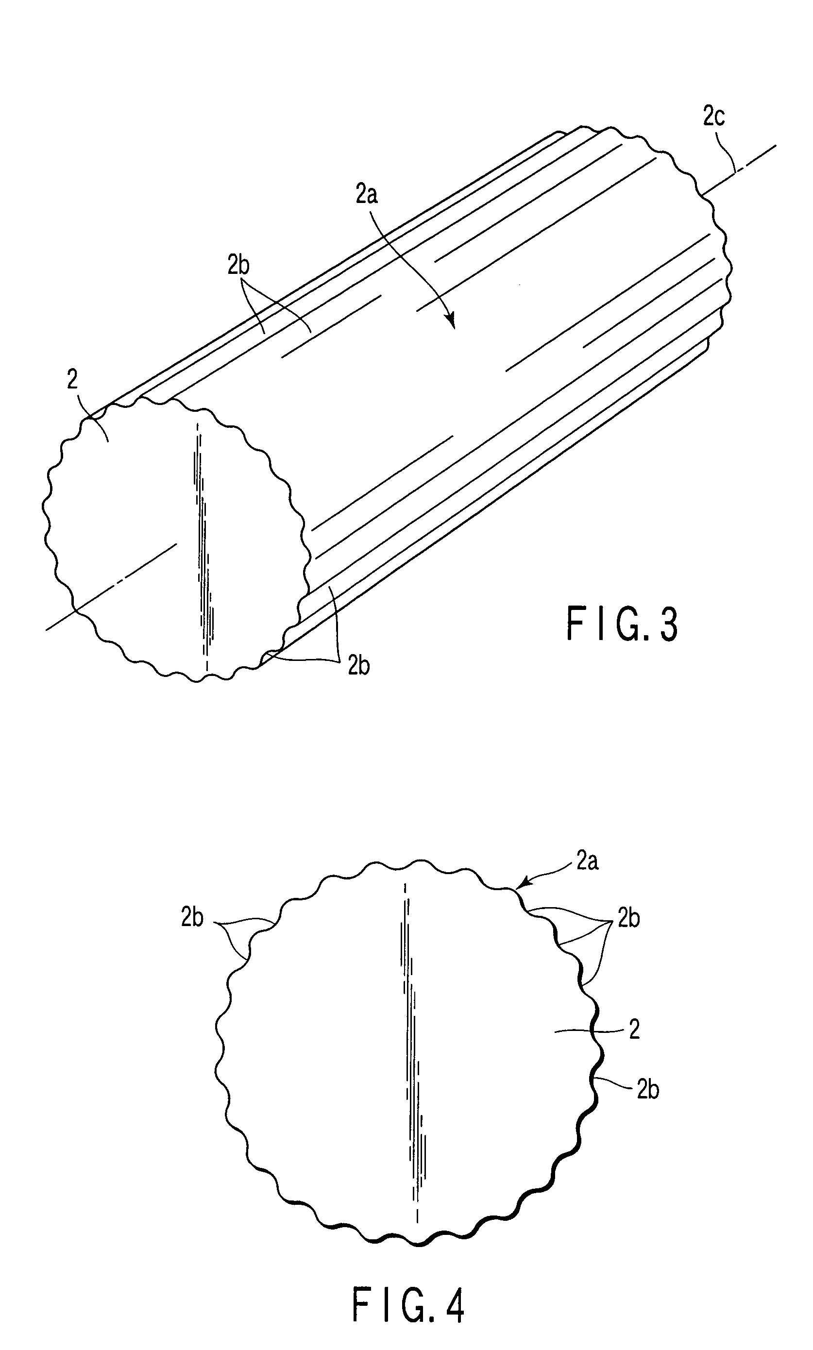
[0044]A fluid dynamic bearing device 1 according to a first embodiment of the present invention will be explained hereinafter with reference to the accompanying drawings FIG. 1 to FIG. 8. As shown in FIG. 1, a fluid dynamic bearing device 1 has a shaft 2 and a bearing 3. The shaft 2 is formed with a plurality of grooves 2b (25 grooves in FIG. 1 to FIG. 4) in an external circumference 2a. In this embodiment, the depth D of the grooves 2b is shown larger than the actual depth to clarify the grooves. For example, when the diameter (maximum) of the shaft 2 is about 10 mm in the fluid dynamic bearing device 1 using air as a fluid, the depth D of the grooves 2b shown in FIG. 2 is about several micrometers.

[0045]The depth D of the grooves 2b is preferably set larger proportional to the diameter of the shaft 2. According to the principle of generating a fluid dynamic, the depth D of the grooves 2b is set to a range of 1–100 μm, not proportional to the shaft diameter, but depending on the ro...


PUM

PropertyMeasurementUnit
diameteraaaaaaaaaa
radiusaaaaaaaaaa
depthaaaaaaaaaa

Abstract

In a method of manufacturing a shaft for the fluid dynamic bearing device, the shaft is formed with a plurality of grooves arranged in and around the external circumference, the surface of the grooves and external circumference with uniform roughness, and machined marks on the surface aligned in the circumferential direction, by controlling the relative vibration of a rod-shaped blank to be machined as the shaft for a fluid dynamic bearing and a grinding wheel (a machining tool) to grind the external circumference of the blank.

Description

CROSS-REFERENCE TO RELATED APPLICATIONS[0001]This is a Continuation Application of PCT Application No. PCT / JP2004 / 001130, filed Feb. 4, 2004, which was published under PCT Article 21(2) in Japanese.[0002]This application is based upon and claims the benefit of priority from prior Japanese Patent Application No. 2003-027383, filed Feb. 4, 2003, the entire contents of which are incorporated herein by reference.BACKGROUND OF THE INVENTION[0003]1. Field of the Invention[0004]The present invention relates to a shaft for a fluid dynamic bearing device, which has an external circumference shaped to generate a fluid dynamic in a clearance to a bearing when rotated relatively to the bearing, a fluid dynamic bearing device having the shaft, and a method of manufacturing the shaft.[0005]2. Description of the Related Art[0006]In a certain type of fluid dynamic bearing, grooves are formed in the direction across the sliding direction in at least one of a bearing surface of a shaft and a bearing,...

Claims


Application Information

Patent Timeline
Patent Type & Authority Patents(United States)
IPC IPC(8): F16C32/06B24B5/22B24B19/02F16C3/02F16C17/02F16C33/10F16C33/14
CPCB24B5/22B24B19/028F16C3/02F16C17/028F16C33/1065F16C33/14F16C17/026F16C2223/42F16C2220/70F16C2220/60F16C17/02F16C33/20
Inventor FURUTA, EIJIROKAYAMA, KENJIMASUDA, MICHIYA
Owner NHK SPRING CO LTD
Why Eureka
Try Eureka