Fractal counterpoise, groundplane, loads and resonators

a fractal counterpoise and ground plane technology, applied in the field of fractal counterpoise, groundplane, loads and resonators, can solve the problems of reducing radiation resistance (“r”), small sized antennas, and focusing too long on the ease of antenna construction, and achieve the effect of reducing resonant frequency

Inactive Publication Date: 2007-05-08
FRACTAL ANTENNA SYST
View PDF2 Cites 49 Cited by
  • Summary
  • Abstract
  • Description
  • Claims
  • Application Information

AI Technical Summary

Benefits of technology

[0028]In one aspect, the present invention provides an antenna with a ground plane or ground counterpoise system that has at least one element whose shape, at least is part, is substantially a deterministic fractal of iteration order N≧1.(The term “ground counterpoise” will be understood to include a ground plane, and / or at least one ground element.) Using fractal geometry, the antenna ground counterpoise has a self-similar structure resulting from the repetition of a design or motif (or “generator”) that is replicated using rotation, and / or translation, and / or scaling. The fractal element will have x-axis, y-axis coordinates for a next iteration N+1 defined by xN+1=f(xN, ybN) and yN+1=g(xN, yN, where xN, yN define coordinates for a preceding iteration, and where f(x,y) and g(x,y) are functions defining the fractal motif and behavior. In another aspect, a vertical antenna is top-loaded with a so-called top-hat assembly that includes at least one fractal element. A fractalized top-hat, assembly advantageously reduces resonant frequency, as well as the physical size and area required for the top-hat assembly.

Problems solved by technology

The unfortunate result is that antenna design has far too long concentrated on the ease of antenna construction, rather than on the underlying electromagnetics.
Experience has long demonstrated that small sized antennas, including loops, do not work well, one reason being that radiation resistance (“R”) decreases sharply when the antenna size is shortened.
Ohmic losses can be minimized using impedance matching networks, which can be expensive and difficult to use.
Unfortunately, radiation resistance R can all too readily be less than 1Ω for a small loop antenna.
Kraus' early research and conclusions that small-sized antennas will exhibit a relatively large ohmic resistance O and a relatively small radiation resistance R, such that resultant low efficiency defeats the use of the small antenna have been widely accepted.
But Kim and Jaggard did not apply a fractal condition to the antenna elements, and test results were not necessarily better than any other techniques, including a totally random spreading of antenna elements.
However, log periodic antennas do not utilize the antenna perimeter for radiation, but instead rely upon an arc-like opening angle in the antenna geometry.
Further, known log-periodic antennas are not necessarily smaller than conventional driven element-parasitic element antenna designs of similar gain.
Attempting to reduce the physical size of such an antenna for a given frequency typically results in a poor feedpoint match (e.g., to coaxial or other feed cable), poor radiation bandwidth, among other difficulties.
Prior art antenna design does not attempt to exploit multiple scale self-similarity of real fractals.
This is hardly surprising in view of the accepted conventional wisdom that because such antennas would be anti-resonators, and / or if suitably shrunken would exhibit so small a radiation resistance R, that the substantially higher ohmic losses O would result in too low an antenna efficiency for any practical use.
Further, it is probably not possible to mathematically predict such an antenna design, and high order iteration fractal antennas would be increasingly difficult to fabricate and erect, in practice.

Method used


Image

  • Fractal counterpoise, groundplane, loads and resonators
  • Fractal counterpoise, groundplane, loads and resonators
  • Fractal counterpoise, groundplane, loads and resonators

Examples


Embodiment Construction

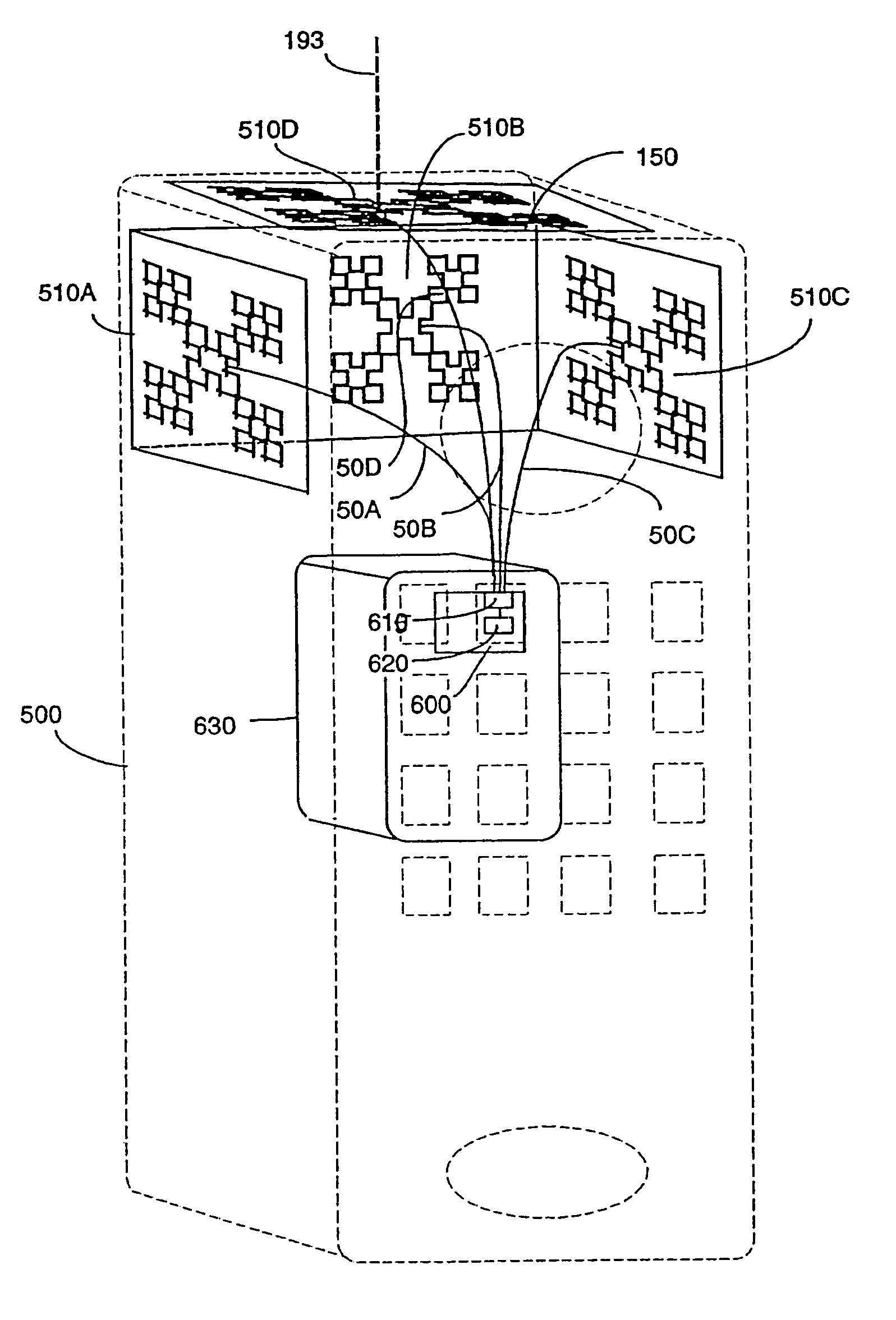
[0103]In overview, in one aspect, the present invention provides an antenna system with a fractal ground counterpoise, e.g., a counterpoise and / or ground plane and / or ground element having at least one element whose shape, at least is part, is substantially a fractal of iteration order N≧1. The resultant antenna is smaller than its Euclidean counterpart, provides close to 50Ω termination impedance, exhibits at least as much gain and more frequencies of resonance than its Euclidean counterpart, including non-harmonically related frequencies of resonance, exhibits a low Q and resultant good bandwidth, acceptable SWR, a radiation impedance that is frequency dependent, and high efficiencies.

[0104]In another aspect, the present invention provides a microstrip patch antenna with at least one element whose shape, at least is part, is substantially a fractal of iteration order N≧1. The resultant antenna is smaller than its Euclidean counterpart, provides close to 50Ω termination impedance, ...


PUM


Abstract

An antenna system includes a fractalized element that may be a ground counterpoise, a top-hat located load assembly, or a microstrip patch antenna having at least one element whose physical shape is at least partially defined as a first or higher iteration deterministic fractal. The resultant fractal element may rely upon an opening angle for performance, and is more compact than non-Euclidean ground counterpoise elements or the like. A vertical antenna system includes a vertical element that may also be a fractal, and a vertical antenna can include vertically spaced-apart fractal conductive and passive elements, and at least one fractal ground element. Various antenna configurations may be fabricated on opposite surfaces of a substrate, including a flexible substrate, and may be tuned by rotating elements relative to each other, and / or by varying the spaced-apart distance therebetween. Fractalized ground counterpoise elements and / or microstrip patch antenna systems may be fabricated on a flexible printed circuit substrate, and / or placed within the support mount of a cellular telephone car antenna.

Description

RELATION TO PREVIOUSLY FILED PATENT APPLICATIONS[0001]This application is a continuation application of Applicant's patent application Ser. No. 10 / 287,240 now issued as U.S. Pat. No. 7,019,695 and entitled Fractal Antenna Ground Counterpoise, Ground Planes, And Loading Elements And Microstrip Patch Antennas With Fractal Structure filed 4 Nov. 2002, which in turn is a continuation application of application Ser. No. 09 / 677,645 now issued as U.S. Pat. No. 6,476,766 and entitled Fractal Antenna Ground Counterpoise, Ground Planes, And Loading Elements And Microstrip Patch Antennas With Fractal Structure, filed 3 Oct. 2000, which in turn is a continuation application of application Ser. No. 08 / 967,375 now issues as U.S. Pat. No. 6,140,975 and entitled Fractal Antenna Ground Counterpoise, Ground Planes, And Loading Elements, filed 7 Nov. 1997, and from Applicant's co-pending patent application Ser. No. 08 / 965,914 now issued as U.S. Pat. No. 6,127,997 and entitled Microstrip Patch Antennas...

Claims


Application Information

Patent Timeline
Patent Type & Authority Patents(United States)
IPC IPC(8): H01Q1/24H01Q1/36H01Q1/38H01Q1/44H01Q9/04H01Q21/20H01Q21/28
CPCH01Q1/243H01Q1/246H01Q1/36H01Q1/38H01Q1/44H01Q1/48H01Q5/371H01Q9/40H01Q21/20H01Q21/205H01Q21/28H01Q15/0093H01Q5/357H01Q9/0407
Inventor COHEN, NATHAN
Owner FRACTAL ANTENNA SYST
Why Eureka
Try Eureka