
Methods for optimizing programmable logic device performance by reducing congestion

Active Publication Date: 2007-04-24
ALTERA CORP
View PDF5 Cites 33 Cited by
  • Summary
  • Abstract
  • Description
  • Claims
  • Application Information

AI Technical Summary

Benefits of technology

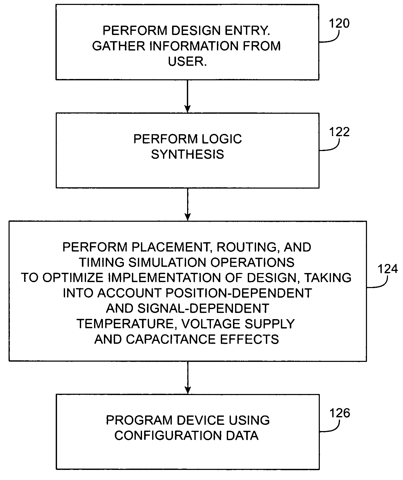
[0012]These position-dependent and signal-dependent effects can be modeled. For example, reductions in transistor drive current with increasing temperature and decreasing power supply voltage and changes in resistances due to temperature variations can be modeled by the computer-aided design tools. The tools can also analyze signal proximity and signal types to estimate cross-talk levels. By taking into account these position-dependent and signal-dependent effects when analyzing the implementations of the logic design, the computer-aided design tools can optimize performance by reducing congestion.

Problems solved by technology

However, as devices become smaller, the effects of circuit congestion become increasingly important to consider.
Congestion can lead to a number of problems.
If circuits are spaced too closely or if too many components are active, the power supply voltage on certain power supply lines may droop due to current loading effects.
Local heating can give rise to hotspots on a device, which can adversely affect circuit performance.
Sometimes signals interact poorly with each other and produce crosstalk.
However, programmable logic device CAD tools do not adequately address the effects of congestion.
For example, while it may be possible to estimate the operating temperature of a programmable logic device, existing tools are not able to identify hotspots or areas where supply voltages droop due to signal loading.
It may be possible to estimate cross-talk noise on certain nodes in a circuit with existing tools, but existing tools are not able to optimize a circuit to reduce cross-talk problems.
Moreover, it is not possible to use custom-logic or application-specific integrated circuit (ASIC) design tools to address these issues, because those tools are incapable of creating custom logic designs for programmable logic devices.

Method used


Image

  • Methods for optimizing programmable logic device performance by reducing congestion
  • Methods for optimizing programmable logic device performance by reducing congestion
  • Methods for optimizing programmable logic device performance by reducing congestion

Examples


Embodiment Construction

[0039]The present invention relates to programmable logic device integrated circuits. The invention also relates to tools and methods for designing and programming optimized programmable logic devices.

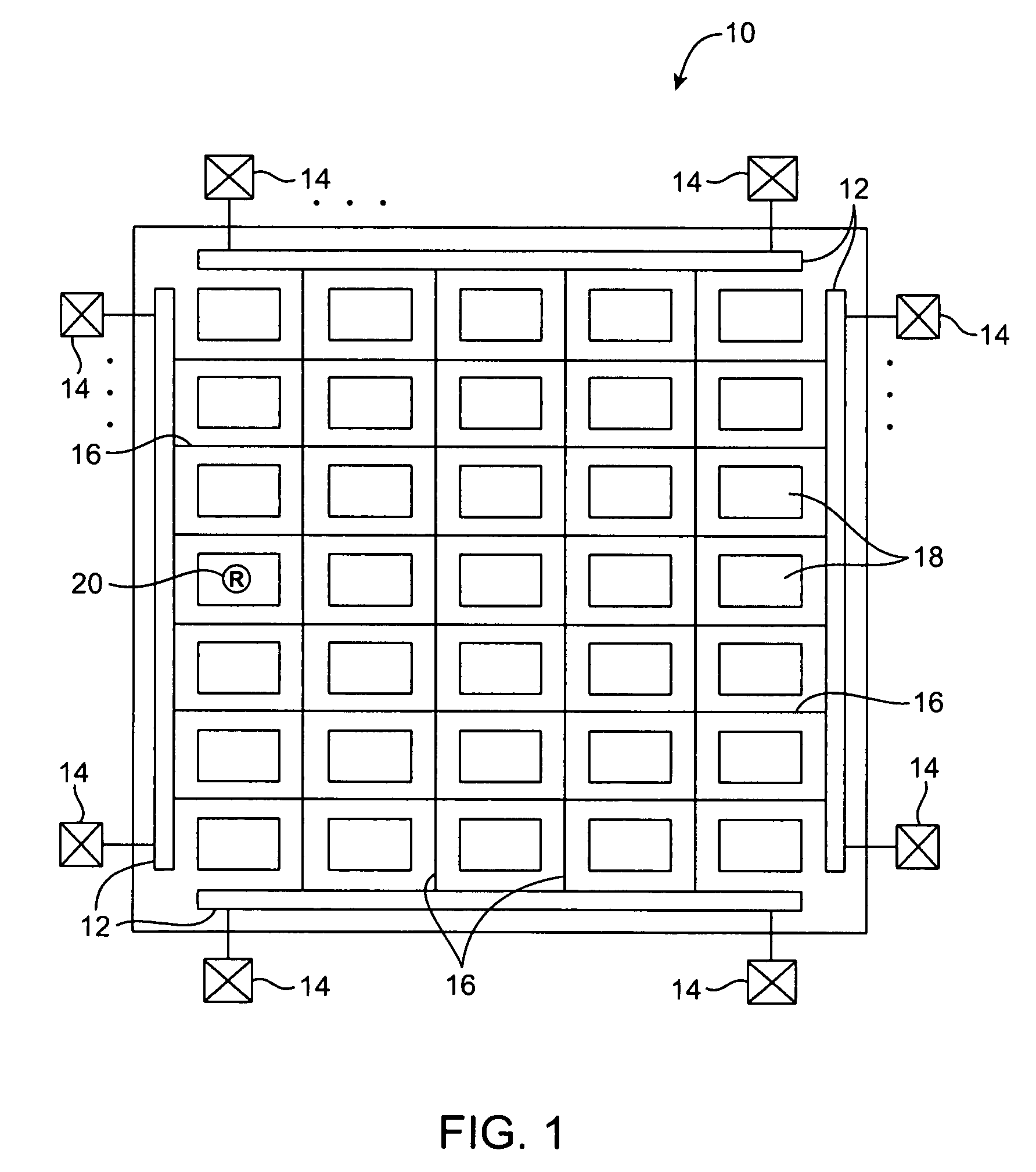
[0040]Programmable logic devices are integrated circuits that can be configured by a user to perform custom logic functions. Electrically-programmed programmable logic devices are configured (“programmed”) by loading configuration data into the device. The configuration data selectively turns on and off components of the device's circuitry and thereby customizes the logic on the device. Mask-programmed programmable logic devices are similar to electrically-programmed programmable logic devices, but are customized using customized lithographic masks based on the configuration data rather than by electrically loading the configuration data into the device.

[0041]The present invention may be used in the context of any integrated circuit that has circuitry that can be configured by a user t...


PUM


Abstract

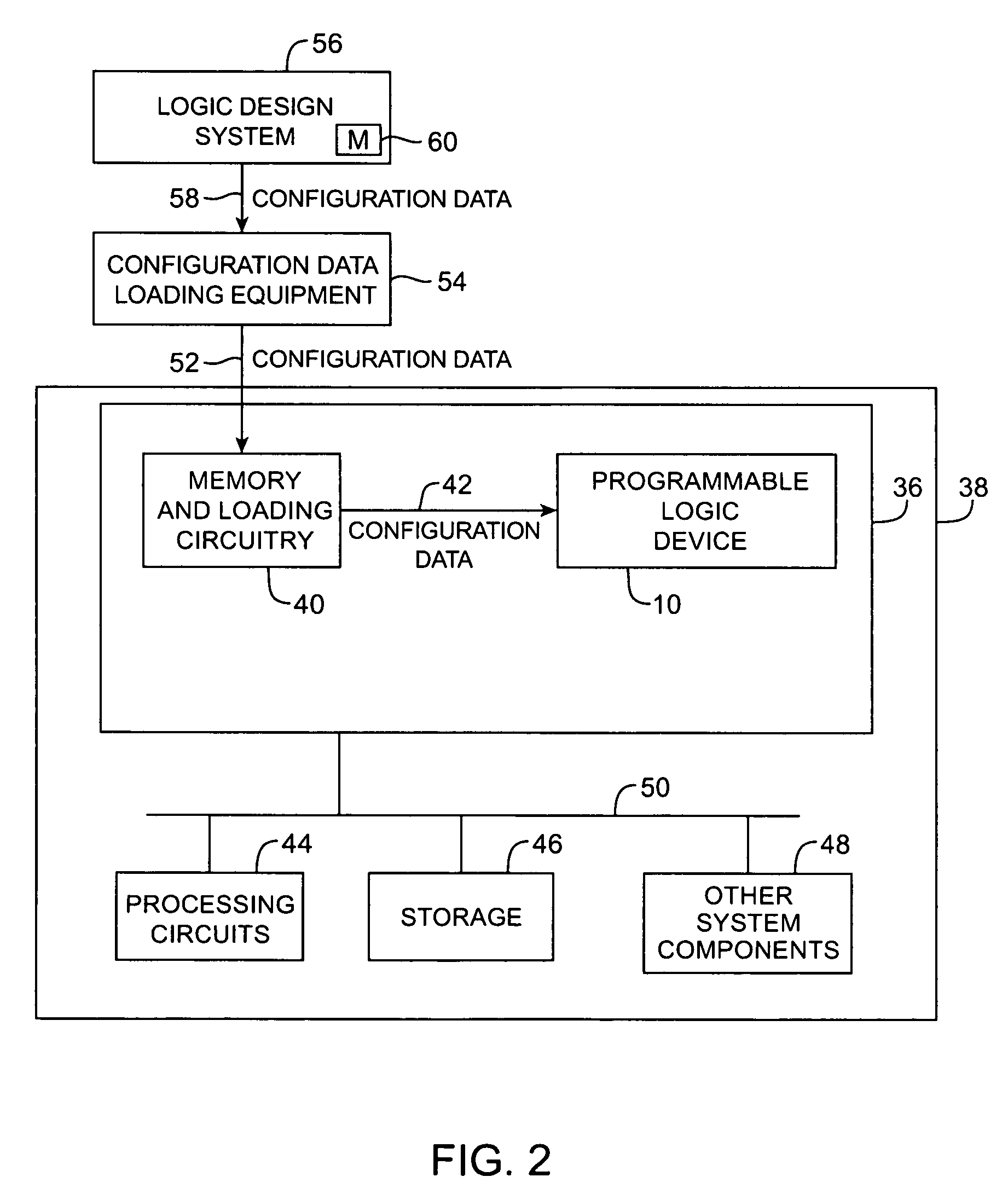
Methods and apparatus for designing and producing programmable logic devices are provided. A logic design system may be used to analyze various implementations of a desired logic design for a programmable logic device integrated circuit. The logic design system may be used to produce configuration data for the programmable logic device in accordance with an optimized implementation. A logic circuit for a programmable logic device can be analyzed by taking into account the effects of hotspots, power supply voltage drops, and signal congestion on device performance. By modeling the performance of transistors and other components using position-dependent and signal-dependent variables such as temperature, voltage, and capacitance, the effects of congestion on device performance can be characterized and an optimum implementation of the logic design in a programmable logic device can be obtained.

Description

BACKGROUND OF THE INVENTION[0001]This invention relates to programmable logic devices, and more particularly, to optimizing logic designs for programmable logic devices by taking into account the effects of congestion.[0002]Programmable logic devices are a type of integrated circuit that can be programmed by a user to implement a desired custom logic function. In a typical scenario, a logic designer uses computer-aided design (CAD) tools to design a custom logic circuit. These tools use information on the hardware capabilities of a given programmable logic device to help the designer implement the custom logic circuit using the resources available on that given programmable logic device. To ensure that the customized programmable logic device performs satisfactorily, the computer-aided design tools optimize the placement and routing of resources on the device.[0003]As semiconductor fabrication methods improve, it is becoming possible to fabricate transistors and other integrated cir...

Claims


Application Information

Patent Timeline
IPC IPC(8): G06F17/50
CPCG06F17/5036G06F17/5054G06F30/34G06F30/367
Inventor RAHIM, IRFANLIU, YOW-JUANG BILL
Owner ALTERA CORP
Learn More