
Infrared array detection device

a detection device and infrared array technology, applied in the direction of optical radiation measurement, material analysis using wave/particle radiation, instruments, etc., can solve the problems of inability to obtain uniform detection sensitivity, miniaturization and integration of the device, etc., and achieve the effect of higher thermal conductivity

Inactive Publication Date: 2007-04-24
HAMAMATSU PHOTONICS KK
View PDF12 Cites 2 Cited by
  • Summary
  • Abstract
  • Description
  • Claims
  • Application Information

AI Technical Summary

Benefits of technology

[0004]An object of the present invention is to provide an infrared detector array capable of integrating a plurality of infrared detecting pixels and making their detection sensitivity sufficiently high and uniform.
[0005]Generally, in an infrared detector array, it is essential that the detection sensitivity is high and uniform. However, in the above-described conventional infrared detector array, when heat is transferred from the infrared absorbing film to the thermocouples, part of the heat may be transferred to the substrate. The thermoelectric conversion efficiency is then decreased, and accordingly the detection sensitivity is decreased. In order to prevent the detection sensitivity from decreasing, the substrate is processed into a diaphragm structure by etching the substrate from its backside. In the case of the diaphragm structure, the hot junctions of the thermocouples are arranged above a thin plate portion of the substrate, and the cold junctions of the thermocouples are arranged above a thick plate portion. This reduces the loss due to the heat conductivity of the substrate.

Problems solved by technology

This leads to a problem that the infrared detectors have various thermoelectric conversion efficiency, thereby failing to obtain uniform detection sensitivity.
However, such a method is not preferred in practice because it has difficulty in miniaturization and integration of the device.

Method used


Image

  • Infrared array detection device
  • Infrared array detection device
  • Infrared array detection device

Examples


Embodiment Construction

[0030]Referring to the drawings, preferred embodiments of the present invention will be described in detail. In the drawings, the same or equivalent parts will be given the same reference numerals or letters, and redundant descriptions thereof will be omitted.

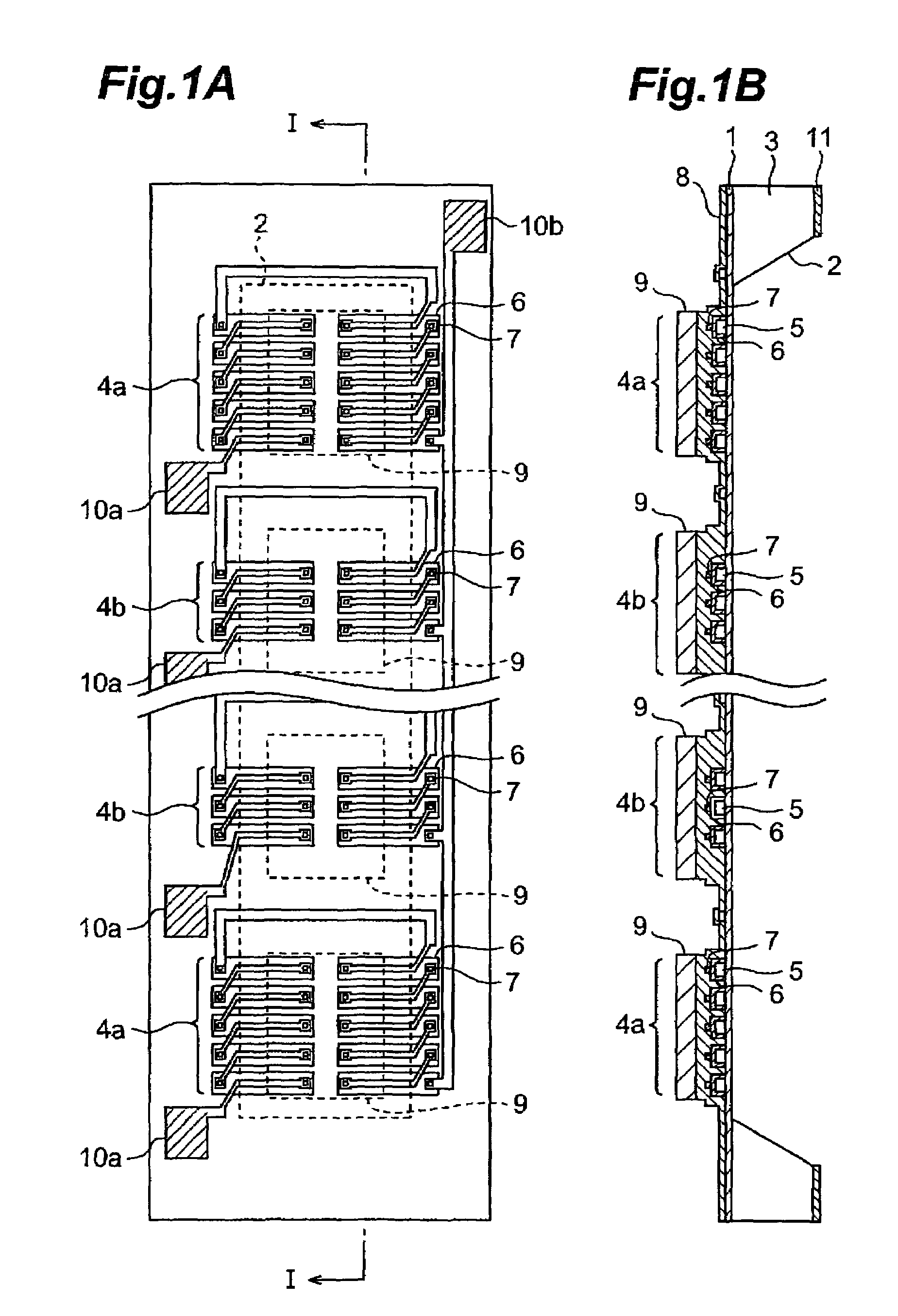
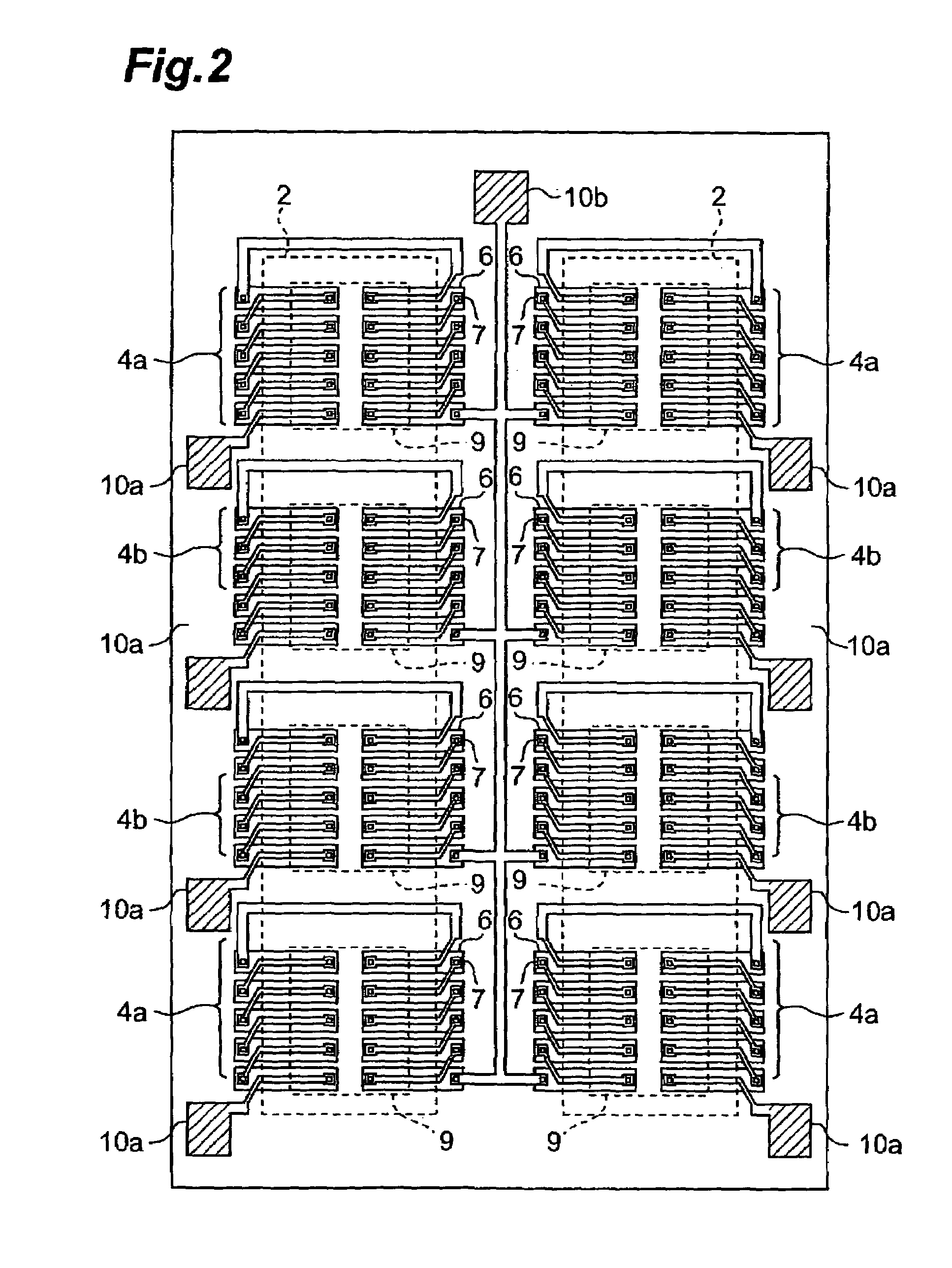
[0031]FIG. 1A is a view showing a thermophila pattern of an infrared detector array according to a first embodiment. FIG. 1B is a sectional view taken along the line I—I in FIG. 1A. As shown, a support member having a diaphragm structure comprises a thin film 1 and a frame 3 made of silicon. The frame 3 has a rectangular (square or oblong) concave portion 2. The frame 3 supports the periphery portion of the thin film 1. Infrared detection pixels 4a and 4b are arranged on the thin film 1 in a one-dimensional array pattern.

[0032]The infrared detecting pixels 4a arranged in both end portions and the infrared detecting pixels 4b arranged in the intermediate portion are different in the number of thermocouples constituting the therm...


PUM


Abstract

In an infrared detector array according to the present invention, on a thin film with a periphery portion supported by a frame, three or more infrared detecting pixels are arranged in an array pattern so that the hot junctions of thermocouples are arranged above a concave portion and the cold junctions thereof are arranged above the frame. Compensation means is provided which compensates for a difference between the detection sensitivity of the infrared detecting pixel arranged in a peripheral end portion and the detection sensitivity of the infrared detecting pixel arranged in an intermediate portion based on a correlation between electromotive force extracted when the infrared detecting pixel is illuminated with infrared radiation and its position. Owing to this configuration, a plurality of infrared detecting pixels can be integrated and the sensitivity thereof can be made sufficiently high and uniform.

Description

TECHNICAL FIELD[0001]The present invention relates to an infrared detector array, and in particular, to an infrared detector array in which three or more infrared detecting pixels are formed in an array.BACKGROUND ART[0002]As a conventional thermophila detector, Japanese Patent Publication No. 2663612 discloses a thermophila which is constituted of a plurality of series-connected thermocouples comprised of a p-type semiconductor and an n-type semiconductor. In such an infrared detector, the Seebeck effect is used. That is, the amount of infrared radiation (quantity of heat), which is incident on the infrared detector, is measured based on the electromotive force generated by a temperature difference between hot junctions and cold junctions of the thermocouples when the heat generated by absorption of infrared radiation is transferred to the thermocouples in an infrared absorbing film.[0003]The above-mentioned conventional infrared detector is used as, for example, a pixel of an infr...

Claims


Application Information

Patent Timeline
Patent Type & Authority Patents(United States)
IPC IPC(8): G01J5/12G01J5/16
CPCG01J5/12G01J5/16H01L31/09
Inventor SHIBAYAMA, KATSUMI
Owner HAMAMATSU PHOTONICS KK
Learn More