
Heat exchanger

a technology of heat exchanger and heat transfer material, which is applied in the direction of heat exchange apparatus safety devices, electrochemical generators, lighting and heating apparatus, etc., can solve the problems of difficult to apply insulating material in a state free of pinholes, deteriorating heat transfer performance, and difficult to achieve the effect of reducing the number of pinholes and reducing the number of holes

Inactive Publication Date: 2007-04-24
DENSO CORP
View PDF18 Cites 3 Cited by
  • Summary
  • Abstract
  • Description
  • Claims
  • Application Information

AI Technical Summary

Benefits of technology

The technical effect of this patent is to provide a heat exchanger that can be insulated from a fuel-cell without significantly deteriorating its cooling performance. The heat exchanger comprises a plurality of stacked tubes and resin tanks coupled to the ends of the tubes, with the tubes formed in two layers of a high heat conductivity resin and an insulative resin. This double-layer structure allows the cooling liquid to flow through the heat exchanger while being insulated from outside, improving heat transfer and preventing contamination of the cooling liquid. The use of a resin material for the tubes reduces weight and cost, and an adhesive layer is formed on the surface of the tubes for easy coupling with the tanks and fins. The insulative resin portion is formed on the inside of the tubes and the high heat conductivity resin portion on the outside, with the high heat conductivity resin containing a metal-containing resin.

Problems solved by technology

The heat exchanger configured of the insulating material described above, however, has a much lower heat conductivity than the configuration of an aluminum material (about one thousandth of the heat conductivity of aluminum), and therefore the heat transfer performance is deteriorated.
Thus, as the insulation characteristic cannot be maintained, the heat conductivity cannot be easily improved.
Depending on the shape, therefore, some parts may not be covered and it is very difficult to apply the insulating material in a state free of pinholes (defects).

Method used


Image

  • Heat exchanger
  • Heat exchanger
  • Heat exchanger

Examples


first embodiment

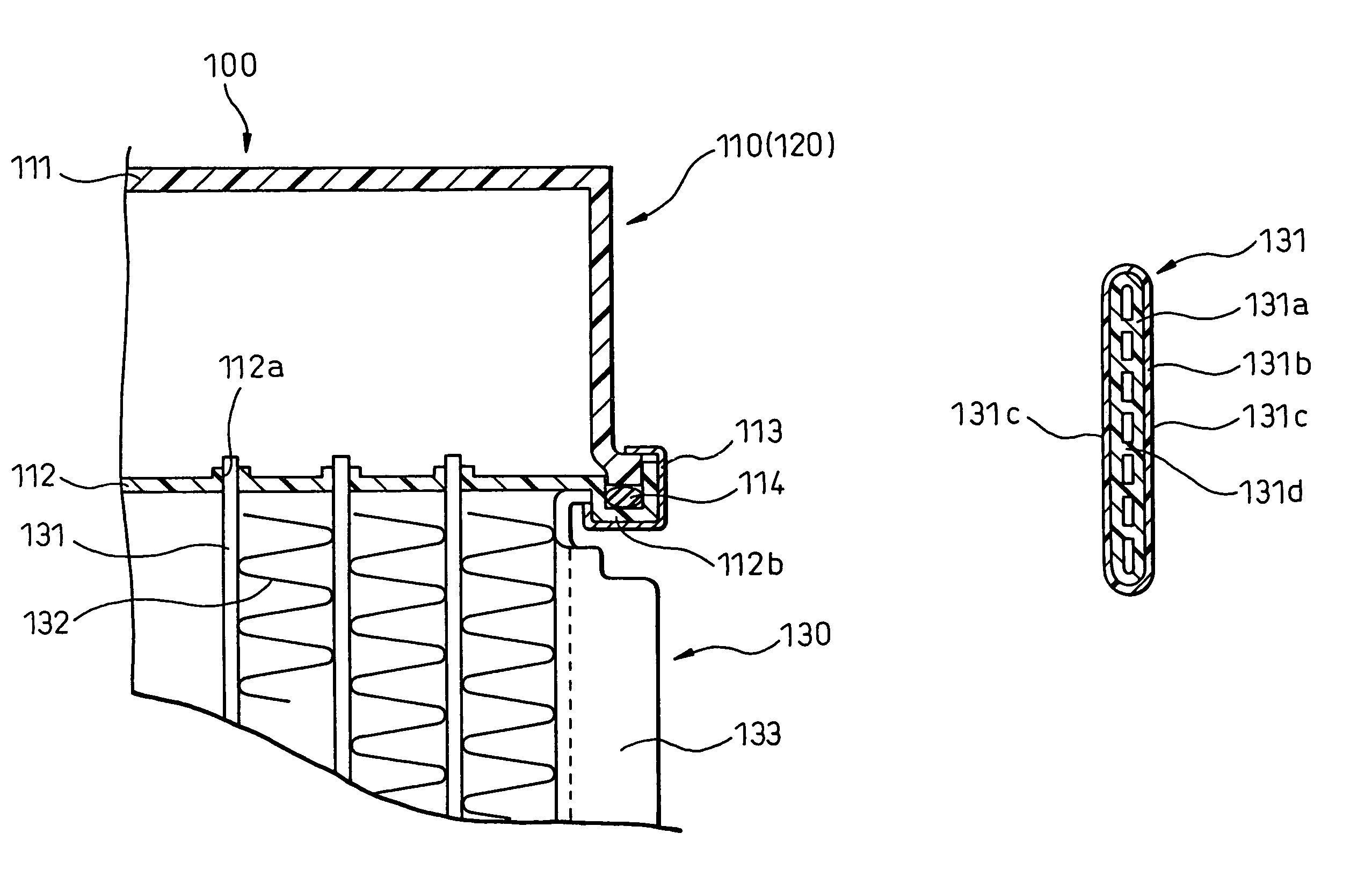
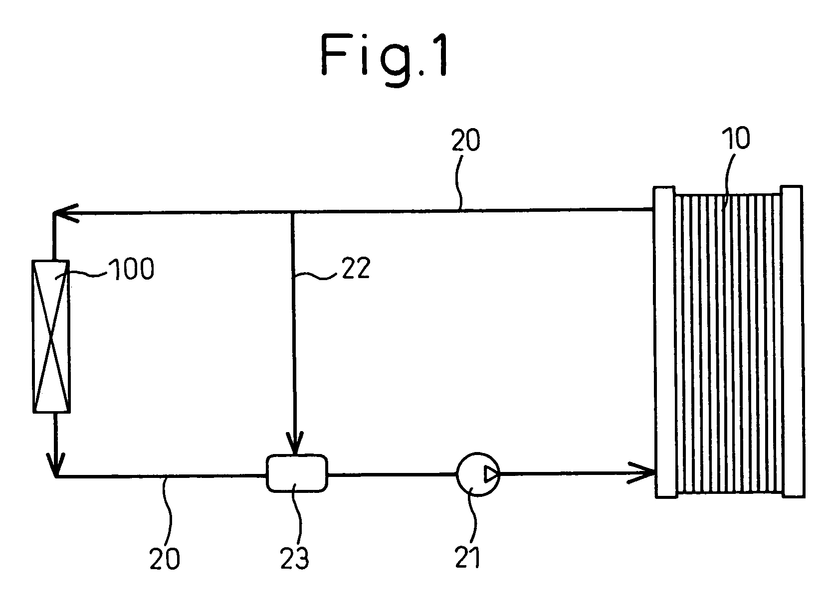
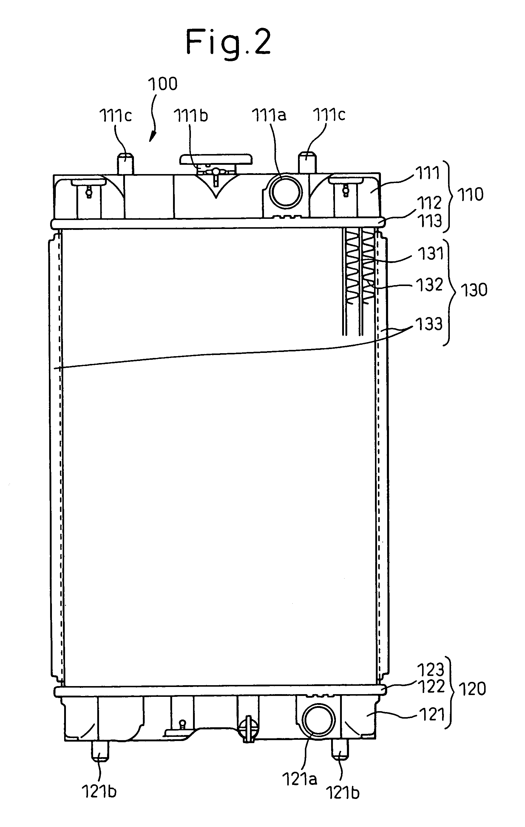
[0026]A heat exchanger according to a first embodiment of the invention is shown in FIGS. 1 to 4. This embodiment is an application of the invention to a radiator 100 for cooling the cooling water passed through a fuel-cell 10. This radiator is mounted on a fuel-cell powered vehicle having a motor driven with the fuel-cell 10 as a power supply. FIG. 1 is a schematic diagram showing the whole fuel-cell cooling system according to the invention, FIG. 2 a front view showing a general configuration of a radiator 100, FIG. 3 an enlarged sectional view showing the neighborhood of the joint between tubes 131 and a plate portion 112, and FIG. 4 a sectional view showing one of the tubes 131.

[0027]First, the cooling system of the fuel-cell 10 is explained briefly with reference to FIG. 1. The fuel-cell 10 generates electric power by a chemical reaction between hydrogen and oxygen, as is well known, and includes a fuel cell stack having a plurality of series-connected cells with high polyelect...


PUM

PropertyMeasurementUnit
temperatureaaaaaaaaaa
heat conductivityaaaaaaaaaa
structureaaaaaaaaaa

Abstract

A heat exchanger having a plurality of stacked tubes (131) and tanks (110, 120) formed of resin and coupled to the longitudinal ends of the tubes (131), wherein the cooling liquid flowing in a fuel-cell (10) is cooled by being passed through the tubes (131) formed of double layers including a high heat conductivity resin portion (131a) and an insulative resin portion (131b).

Description

TECHNICAL FIELD[0001]This invention relates to a heat exchanger for cooling the fuel-cell of a fuel-cell powered vehicle.BACKGROUND ART[0002]In recent years, a clean fuel-cell powered vehicle, which does not generate any material harmful to the environment, has been under development. The fuel-cell must be cooled by a heat exchanger. During power generation by the fuel-cell, a high voltage is impressed on a cooling medium (such as the cooling water), and therefore the heat exchanger must be electrically insulated.[0003]As a method designed to meet this requirement, the heat exchanger is configured of an insulating material (thermoplastic polymer) (Japanese Unexamined Patent Publication No. 63-311084) or the inner surface of a metal heat exchanger is covered with an insulating material (coated with resin) (Japanese Unexamined Patent Publication No. 2003-181628).[0004]The heat exchanger configured of the insulating material described above, however, has a much lower heat conductivity ...

Claims


Application Information

Patent Timeline
Patent Type & Authority Patents(United States)
IPC IPC(8): F28F13/18F28F21/06
CPCF28D1/05383F28F13/18F28F21/062F28F2265/24F28F2275/025H01M8/04029F28F2255/143Y02E60/50
Inventor SONODA, YOSHIHIKOOSAKABE, HIROYUKIOMAE, MASAHIRO
Owner DENSO CORP
Learn More