
Battery module and battery pack including the same

a battery module and battery pack technology, applied in the field of batteries and battery packs, can solve the problems of affecting the performance of secondary batteries, increasing the risk of explosion or ignition, so as to improve the rigidity, improve the cooling performance, and improve the rigidity. the effect of vibration and impa

Pending Publication Date: 2022-08-04
LG ENERGY SOLUTION LTD
View PDF0 Cites 0 Cited by
  • Summary
  • Abstract
  • Description
  • Claims
  • Application Information

AI Technical Summary

Benefits of technology

This patent aims to improve the cooling performance of a battery module by integrating cooling and structurally deforming the cooling plate to increase rigidity against vibration and impact. This prevents excessive deformation of the module frame, reducing the likelihood of refrigerant leakage and maintaining cooling performance. The technical effect of this patent is improved cooling performance through a structural solution.

Problems solved by technology

When the temperature of the secondary battery rises higher than an appropriate temperature, the performance of the secondary battery may be deteriorated, and in the worst case, there is also a risk of an explosion or ignition.
In particular, a large number of secondary batteries, that is, a battery module or a battery pack having battery cells, can add up the heat generated from the large number of battery cells in a narrow space, so that the temperature can rise more quickly and severely.
In other words, a battery module in which a large number of battery cells are stacked, and a battery pack equipped with such a battery module can obtain high output, but it is not easy to remove heat generated from the battery cells during charging and discharging.
When the heat dissipation of the battery cell is not properly performed, deterioration of the battery cells is accelerated, the lifespan is shortened, and the possibility of explosion or ignition increases.
Moreover, in the case of a middle or large-sized battery module contained in a vehicle battery pack, it is frequently exposed to direct sunlight and can be subjected to high-temperature conditions such as summer or desert areas.
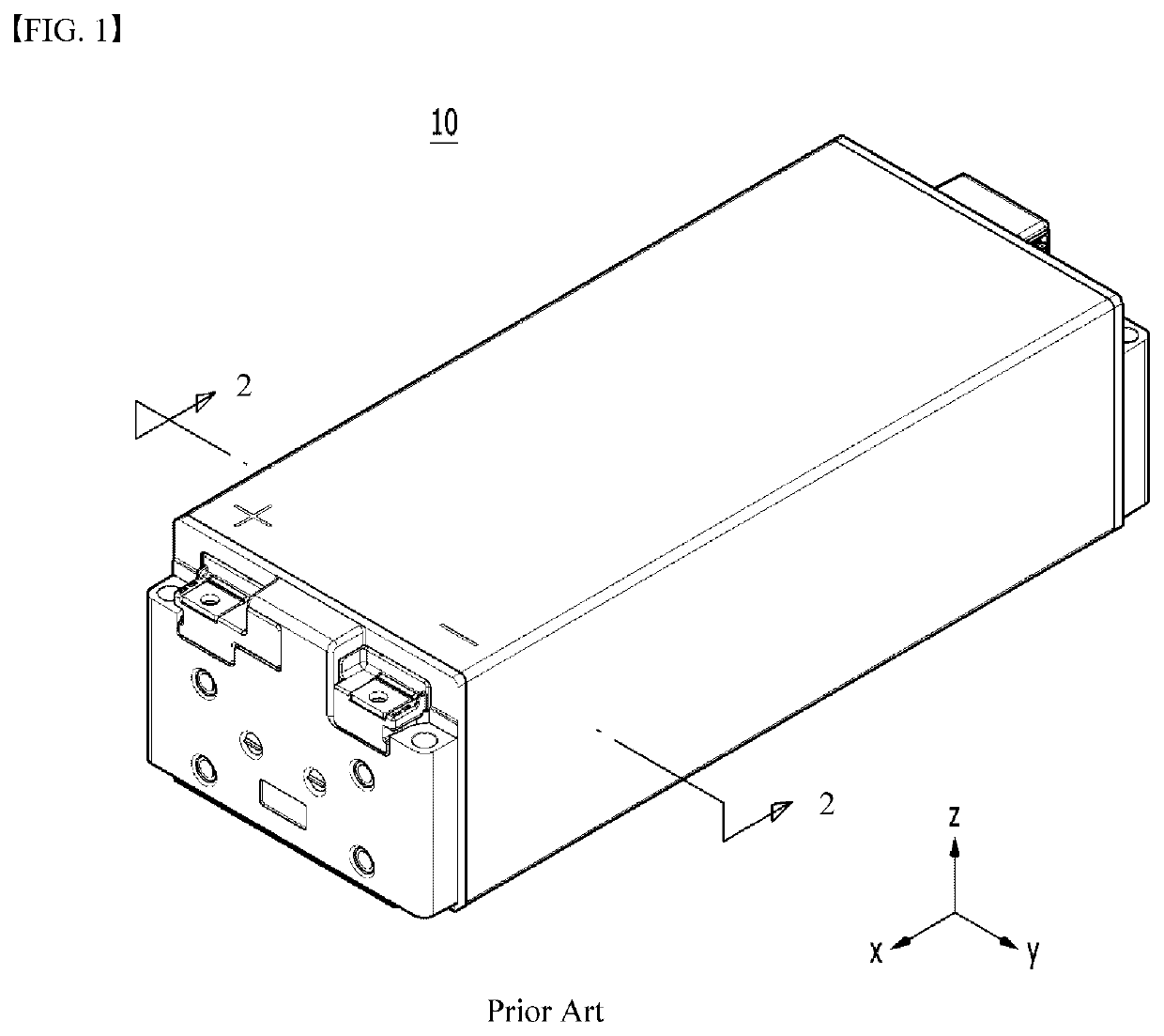
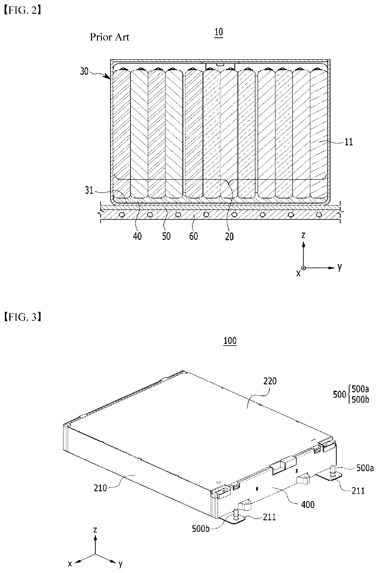
By the way, in the case of the conventional battery module 10, the heat transfer path is complicated as described above and thus, it is difficult to effectively transfer the heat generated from the battery cell 11.

Method used


Image

  • Battery module and battery pack including the same
  • Battery module and battery pack including the same
  • Battery module and battery pack including the same

Examples


Embodiment Construction

Technical Problem

[0018]It is an object of the present disclosure to provide a battery module having improved cooling performance, and a battery pack including the same.

[0019]However, the technical problem to be solved by embodiments of the present disclosure is not limited to the above-described problems, and can be variously expanded within the scope of the technical idea included in the present disclosure.

Technical Solution

[0020]According to one embodiment of the present disclosure, there is provided a battery module comprising: a battery cell stack in which a plurality of battery cells are stacked in a stacking direction, a module frame for housing the battery cell stack, the module frame including a bottom portion, a thermal conductive resin layer located between the bottom portion of the module frame and the battery cell stack, and a heat sink located below the bottom portion of the module frame, wherein the bottom portion of the module frame forms an upper plate attached to th...


PUM

PropertyMeasurementUnit
thermal conductiveaaaaaaaaaa
conductiveaaaaaaaaaa
thicknessaaaaaaaaaa

Abstract

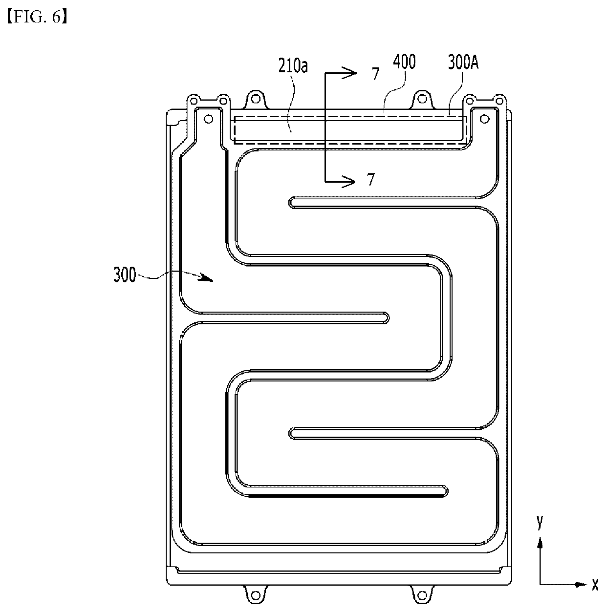
A battery module includes a battery cell stack in which a plurality of battery cells are stacked, a module frame for housing the battery cell stack, a thermal conductive resin layer located between a bottom portion of the module frame and the battery cell stack, and a heat sink located below a bottom portion of the module frame. The bottom portion of the module frame has an upper plate of the heat sink, and an avoidance portion for exposing one end of the bottom portion of the module frame is formed at one end of the heat sink.

Description

TECHNICAL FIELD[0001]Cross Citation with Related Application(s)[0002]This application claims the benefit of Korean Patent Application No. 10-2020-0052256 filed on Apr. 29, 2020 with the Korean Intellectual Property Office, the disclosure of which is incorporated herein by reference in its entirety.[0003]The present disclosure relates to a battery module and a battery pack including the same, and more particularly, to a battery module having improved cooling performance, and a battery pack including the same.BACKGROUND ART[0004]In modern society, as portable devices such as a mobile phone, a notebook computer, a camcorder and a digital camera has been daily used, the development of technologies in the fields related to portable devices as described above has been activated. In addition, chargeable / dischargeable secondary batteries are used as a power source for an electric vehicle (EV), a hybrid electric vehicle (HEV), a plug-in hybrid electric vehicle (P-HEV) and the like, in an att...

Claims


Application Information

Patent Timeline
Patent Type & Authority Applications(United States)
IPC IPC(8): H01M10/6556H01M10/647H01M50/211
CPCH01M10/6556H01M10/613H01M50/211H01M10/647H01M50/258H01M50/204H01M50/242H01M50/244H01M10/617H01M10/653H01M10/6554H01M10/6567H01M10/6551Y02E60/10H01M50/209H01M50/20H01M2220/20H01M10/623H01M10/625H01M2220/10Y02T10/70
Inventor LEE, CHANGHUNSEONG, JUNYEOBPARK, MYUNGKI
Owner LG ENERGY SOLUTION LTD
Learn More