
Chisel for a pyromechanical disconnecting device

a technology of pyromechanical and chisel, which is applied in the direction of protective switch operation/release mechanism, circuit-breaking switch, protective switch details, etc., can solve the problems of reducing the service life of the electrical conductor, affecting the component cost, and limiting the cutting power, so as to improve the pressure distribution and expand the bearing area

Inactive Publication Date: 2007-04-17
AUTOLIV DEV AB +2
View PDF9 Cites 25 Cited by
  • Summary
  • Abstract
  • Description
  • Claims
  • Application Information

AI Technical Summary

Benefits of technology

[0006]A goal of the invention is to improve a disconnecting device having a housing in which an electrical conductor is arranged and clamped therein by a lock component, having a cutting plunger and a cutting chisel made of plastic arranged thereon for severing the electrical conductor, and having a pyrotechnic igniter in which a pyrotechnic charge for driving the cutting plunger is arranged in such fashion that the cutting chisel has better cutting power, that is, can sever conductors larger in cross section, with no substantial increase in its manufacturing costs.
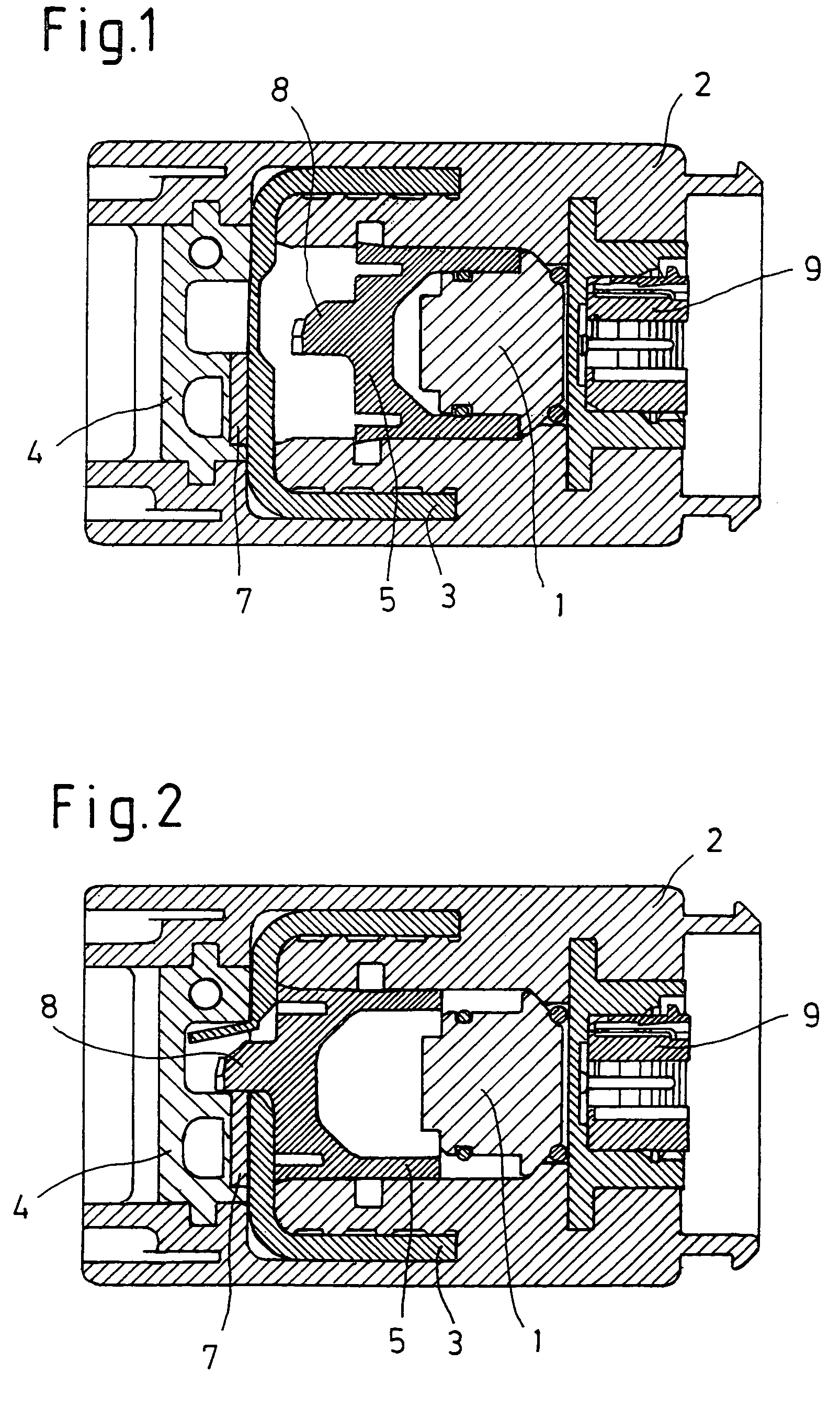
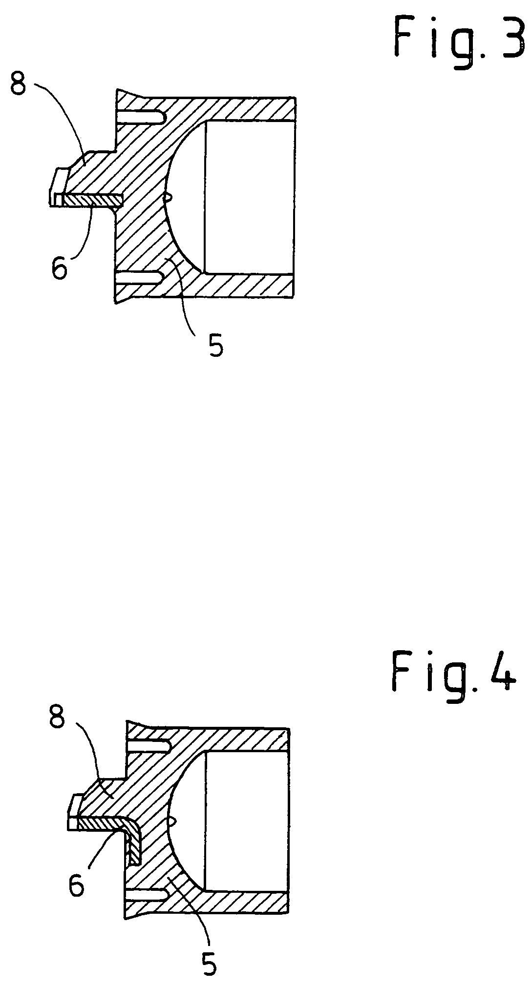
[0009]The edge of the cutting chisel formed by the structural element is preferably made V-shaped, acutely tapered, or obliquely shaped in longitudinal section. The angle of the edge of the cutting chisel on the end face of the structural element advantageously lies between 180 degrees and 90 degrees. The aforesaid shapes of the edge have the advantage that the blade does not immediately impinge with its full width on the separating point of the electrical conductor to be cut but penetrates into the material beginning at two contact points or one contact point respectively. In the case of a V-shaped blade, the cutting force becomes progressively lower with decreasing spreading angle of the two arms of the V.
[0011]In one advantageous embodiment, the structural element of the cutting chisel reaches into the cutting plunger and there extends substantially perpendicularly to the edge. The structural element of the cutting chisel preferably has the shape of an angle or the shape of an L. These shapes of the structural element bring about a better pressure distribution from the edge to the base of the cutting chisel and thus to the cutting plunger when force is exerted on the cutting chisel by the cutting action, thus enlarging the bearing area so as to reduce the danger that the cutting chisel will be pushed through the cutting plunger.

Problems solved by technology

It is a drawback that the cutting power (severance of an electrical conductor with a given cross section) remains limited because of the strength properties of the cutting chisel made of plastic.
If a cutting chisel and the cutting edge are made as a unit, for example of ceramic, this has a negative impact on component costs.

Method used


Image

  • Chisel for a pyromechanical disconnecting device
  • Chisel for a pyromechanical disconnecting device
  • Chisel for a pyromechanical disconnecting device

Examples


Embodiment Construction

[0013]In what follows, the invention will be explained in greater detail with reference to exemplary embodiments. FIG. 1 shows a pyrotechnic disconnecting apparatus for battery shutoff in a motor vehicle, having a pyrotechnic igniter 1 in which a pyrotechnics charge for driving a cutting plunger 5 is arranged. Igniter 1 is fired electrically, the electric feeds being affected via a connector 9 on housing 1. When igniter 1 is fired, the propellant gases formed by the pyrotechnics charge accelerate cutting plunger 5, on which a cutting chisel 8 is arranged, toward an electrical conductor 3, and cutting chisel 8 cuts conductor 3 at a separating point by virtue of its kinetic energy. Electrical conductor 3 is clamped in housing 2 by a component 4 (here also called a lock). A recess in arranged in component 4 in the region of the separating point. The edge of the recess forms a mating edge along which cutting chisel 8 slides when conductor 3 is severed.

[0014]Electrical conductor 3 is a c...


PUM


Abstract

The invention relates to a pyromechanical disconnecting device having a housing (2) in which an electrical conductor (3) is arranged, having a cutting plunger (5) and a cutting chisel (8) made of plastic arranged thereon for severing the electrical conductor (3), and having a pyrotechnic igniter (1) in which a pyrotechnic charge is arranged for driving the cutting plunger (5), the cutting chisel (8) having an edge that slides along a mating edge of the housing (2) or of a component (4) of the housing (2) when the cutting plunger (5) or the cutting chisel (8) is driven and when the electrical conductor (3) is severed.In order to achieve better cutting power, it is proposed that the edge of the cutting chisel (8) and / or the mating edge of the housing (2) or of a component (4) of the housing (2) comprise an inserted structural element (6, 7) having a greater hardness than plastic.

Description

FIELD OF THE INVENTION[0001]This invention relates to a pyromechanical disconnecting device having a housing in which an electrical conductor is arranged and clamped therein by a lock component, having a cutting plunger and a cutting chisel made of plastic arranged thereon for severing the electrical conductor, and having a pyrotechnic igniter in which a pyrotechnic charge for driving the cutting plunger is arranged.BACKGROUND[0002]DE 197 32 650 A1 describes a pyromechanical disconnecting device having a housing in which an electrical conductor is arranged, having a cutting plunger and a cutting chisel made of plastic arranged thereon for severing the electrical conductor, and having a pyrotechnic igniter in which a pyrotechnic charge for driving the cutting plunger is arranged, the cutting chisel having an edge that slides along a mating edge of the housing or of a component of the housing when the cutting plunger or the cutting chisel is driven and when the electrical conductor is...

Claims


Application Information

Patent Timeline
IPC IPC(8): H01H39/00H01H85/175H01H37/76
CPCH01H39/006H01H2039/008B29C45/14
Inventor KORDEL, GERHARDKNAUSS, JURGEN
Owner AUTOLIV DEV AB
Learn More