
Low noise and high gain low noise amplifier

a low noise amplifier and low noise technology, applied in the direction of amplifiers with semiconductor devices/discharge tubes, amplifiers with different amplifiers, etc., can solve the problems of encumbering system performance, power loss increases the nf (noise figure) of the entire receiver, and the limitation of the ability to reduce the common mode noise of the mixer, etc., to achieve low noise, noise figure, and high power gain

Active Publication Date: 2007-04-17
RICHWAVE TECH CORP
View PDF1 Cites 23 Cited by
  • Summary
  • Abstract
  • Description
  • Claims
  • Application Information

AI Technical Summary

Benefits of technology

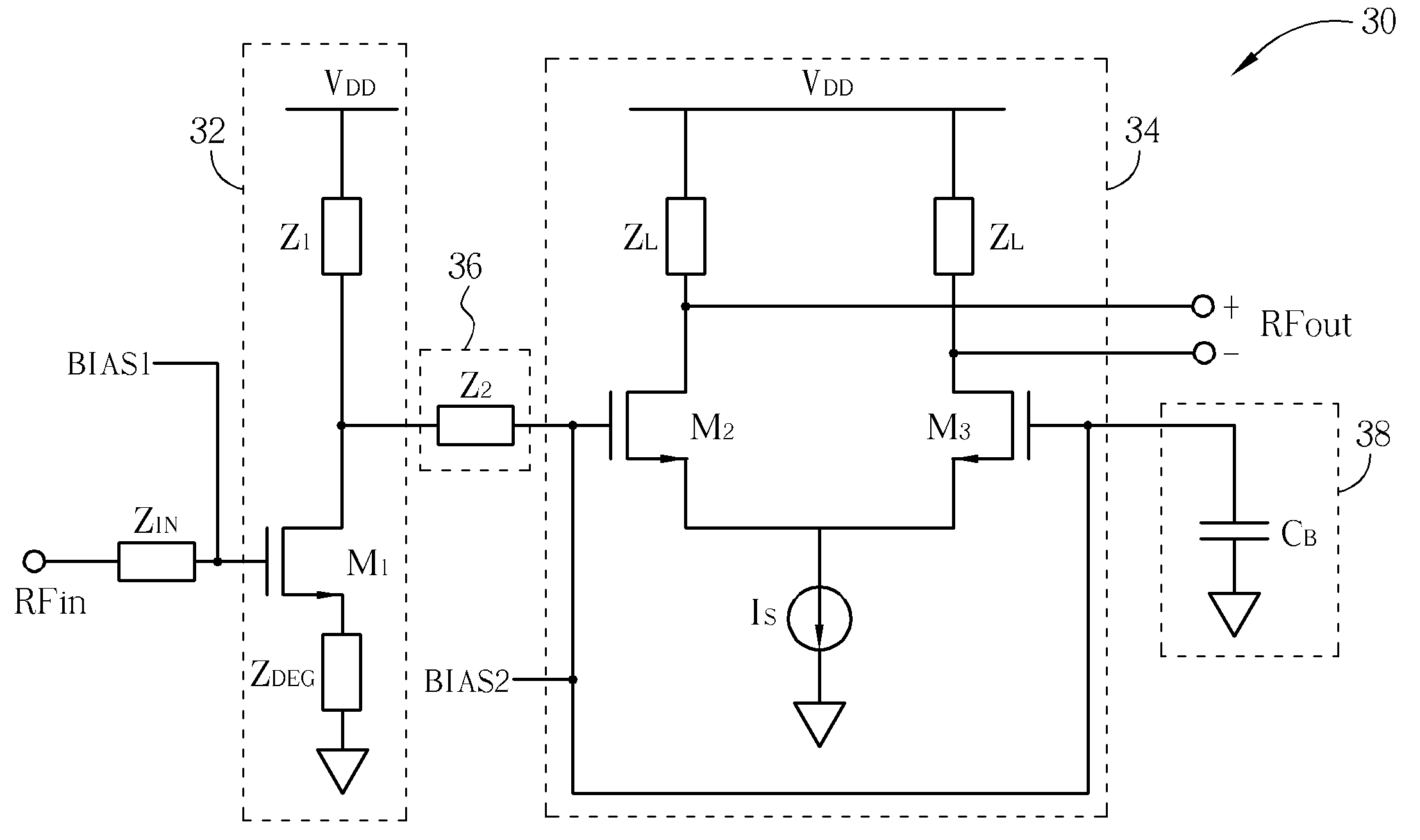
The invention is a low noise amplifier (LNA) with high gain and low noise performance. It consists of a differential amplifier, a pre-amplifier and an impedance matching network. The LNA has low NF, high power gain, and is easy to design compared to prior art. The technical effect of the invention is to provide a high-quality LNA that is easy to use and has superior performance.

Problems solved by technology

This design has limited ability to reduce the common mode noise of the mixer and the signal leaked from the oscillator to the mixer.
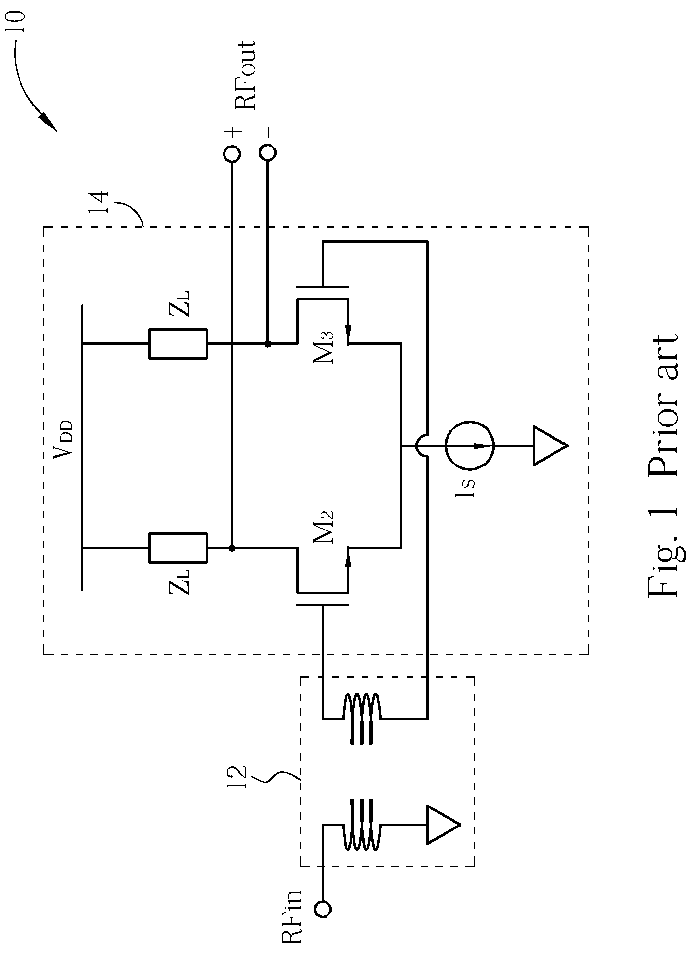
This transformer not only adds extra cost to the capital, but its power loss also increases the NF (Noise Figure) of the entire receiver and encumbers system performance.
The metal coils of the transformer 12 occupy large areas of the circuit layout and add to manufacturing costs.
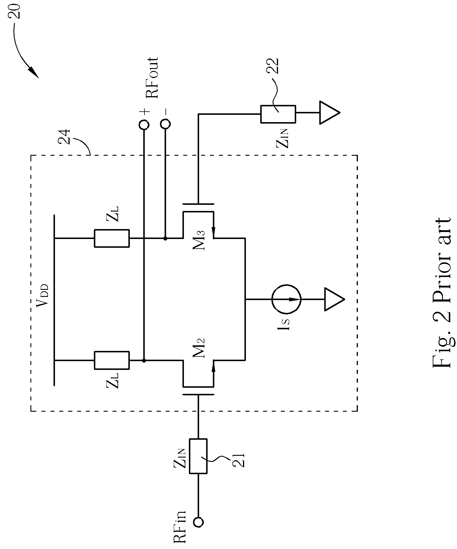
When a differential amplifier is operated at high frequencies, however, the current source Is used to bias the differential pair cannot be viewed as an ideal high impedance current source.
If a metal coil transformer is used to achieve a single-input-to-differential-output LNA structure, large areas on the circuit will be occupied, raising manufacturing costs.
This high frequency characteristic of a non-ideal current source increases the complexity when designing the noise and gain for the LNA.

Method used


Image

  • Low noise and high gain low noise amplifier
  • Low noise and high gain low noise amplifier
  • Low noise and high gain low noise amplifier

Examples


third embodiment

[0033]Please refer to FIG. 5. FIG. 5 is a diagram of a high-gain LNA 50 of the present invention. The LNA 50 is extended from the LNA 40. The LNA 50 includes a pre-amplifier 52, a differential amplifier 54, an impedance matching network 56 and a grounded impedance 58. In the differential amplifier 54 of the LNA 50, sources of the transistors M2 and M3 are in series connection to degeneration inductances ZD2 and ZD3, respectively. The series connection between the sources of the transistors M2 and M3 and the degeneration inductances ZD2 and ZD3 betters the linearity of the differential amplifier 54.

fourth embodiment

[0034]Please refer to FIG. 6. FIG. 6 is a diagram of a high-gain LNA 60 of the present invention. The LNA 60 has a switching structure that provides 2 operating modes: high gain mode and low gain mode. The LNA 60 includes a pre-amplifier 62, a differential amplifier 64, an impedance matching network 66 and a grounded impedance 68. The differential amplifier 64 comprises 6 transistors M2 through M7. Drains of the transistors M4 and M5 are coupled to VDD through an impedance ZL1, separately. The drains of transistor M6 and M7 are coupled to VDD through an impedance ZL2, separately. An impedance ZG1 is coupled between drains of the transistors M4 and M6, and an impedance ZG2 is coupled between drains of the transistors M5 and M7. When the differential amplifier 64 operates under high gain mode, the transistors M4 and M5 remain on and the transistors M6 and M7 remain off. When a high frequency signal enters the differential amplifier 64, one part of the signal travels through the transi...


PUM


Abstract

high-gain and low-noise low noise amplifier (LNA) includes a differential amplifier, a pre-amplifier and an impedance matching network. The differential amplifier includes a first input end and a second input end coupled to a grounded impedance. The pre-amplifier includes an input end and an output end. The impedance matching network is coupled between the first input end of the differential amplifier and the output end of the pre-amplifier for matching an input impedance of the differential amplifier with an output impedance of the pre-amplifier. The present invention provides a LNA structure with low noise, high gain and easy design.

Description

BACKGROUND OF INVENTION[0001]1. Field of the Invention[0002]The present invention relates to a low noise amplifier, and more particularly, to a low-noise and high-gain low noise amplifier.[0003]2. Description of the Prior Art[0004]With the widespread usage of cellular phones, mobile communication has become an integral part of daily life. Many design companies endeavor to improve every circuit block of the communication system. Low noise amplifiers (LNAs) belong to the receiver part of a communication system, with the function to enlarge received signals and to suppress the receiver's noise.[0005]Commonly, LNA structure is based on a single-input-to-single-output design. In this structure the input end of the mixer that follows the LNA has to be single-ended as well. This design has limited ability to reduce the common mode noise of the mixer and the signal leaked from the oscillator to the mixer. Applying a differential output structure to the LNA can solve the problem. The most si...

Claims


Application Information

Patent Timeline
Patent Type & Authority Patents(United States)
IPC IPC(8): H03F3/45H03F3/191
CPCH03F1/26H03F3/45183H03F3/45188H03F2200/294H03F2200/372H03F2203/45288H03F2203/45592H03F2203/45621
Inventor SU, JIONG-GUANGLIOU, TSYR-SHYANGWONG, SHYH-CHYI
Owner RICHWAVE TECH CORP
Learn More