SiGe differential cascode amplifier with miller effect resonator

a technology of cascode amplifier and miller effect, which is applied in differential amplifiers, amplifiers with semiconductor devices/discharge tubes, amplifier details, etc., can solve the problems of reducing the maximum power that can be output from an amplifier, increasing the intrinsic capacitance of the transistor, and reducing the breakdown voltage of the transistor, so as to reduce the current amplification

Inactive Publication Date: 2007-04-17
COBHAM DEFENSE ELECTRONICS SYST CORP
View PDF12 Cites 9 Cited by
  • Summary
  • Abstract
  • Description
  • Claims
  • Application Information

AI Technical Summary

Benefits of technology

[0006]In one embodiment of the high-power, high frequency amplifier, a differential common-emitter amplifier provides voltage amplification. The differential arrangement allows the total voltage swing of the amplifier to be substantially twice the breakdown voltage of the transistors. Current amplification is then provided by a differential common-base amplifier connected in cascode with the common-emitter front-end, voltage amplifier. By making the cascode connection via appropriately chosen resonators, acting primarily as inductors, the negative current feed-back (an example of the Miller effect) that reduces the current amplification at high frequency operation, can be significantly reduced, or resonated out, at the amplifier's operational frequency.

Problems solved by technology

The high speed switching of SiGe bipolar transistors, however, comes at the cost of reduced transistor breakdown voltage and increased intrinsic capacitance of the transistors.
These drawbacks become particularly troublesome when attempting to implement SiGe class A high-power amplifiers capable of operating at high frequencies (greater than 1 GHz).
The reduced break down voltage, therefore, significantly reduces the maximum power that can be output from an amplifier using SiGe transistors.
In addition, the high intrinsic capacitance of the transistors results in significant negative feedback of current at high frequencies (greater than 1 GHz), further reducing the power output of such amplifiers.
And finally, the lack of via holes causes high inductive feedback which greatly decreases gain.

Method used


Image

  • SiGe differential cascode amplifier with miller effect resonator
  • SiGe differential cascode amplifier with miller effect resonator
  • SiGe differential cascode amplifier with miller effect resonator

Examples


Embodiment Construction

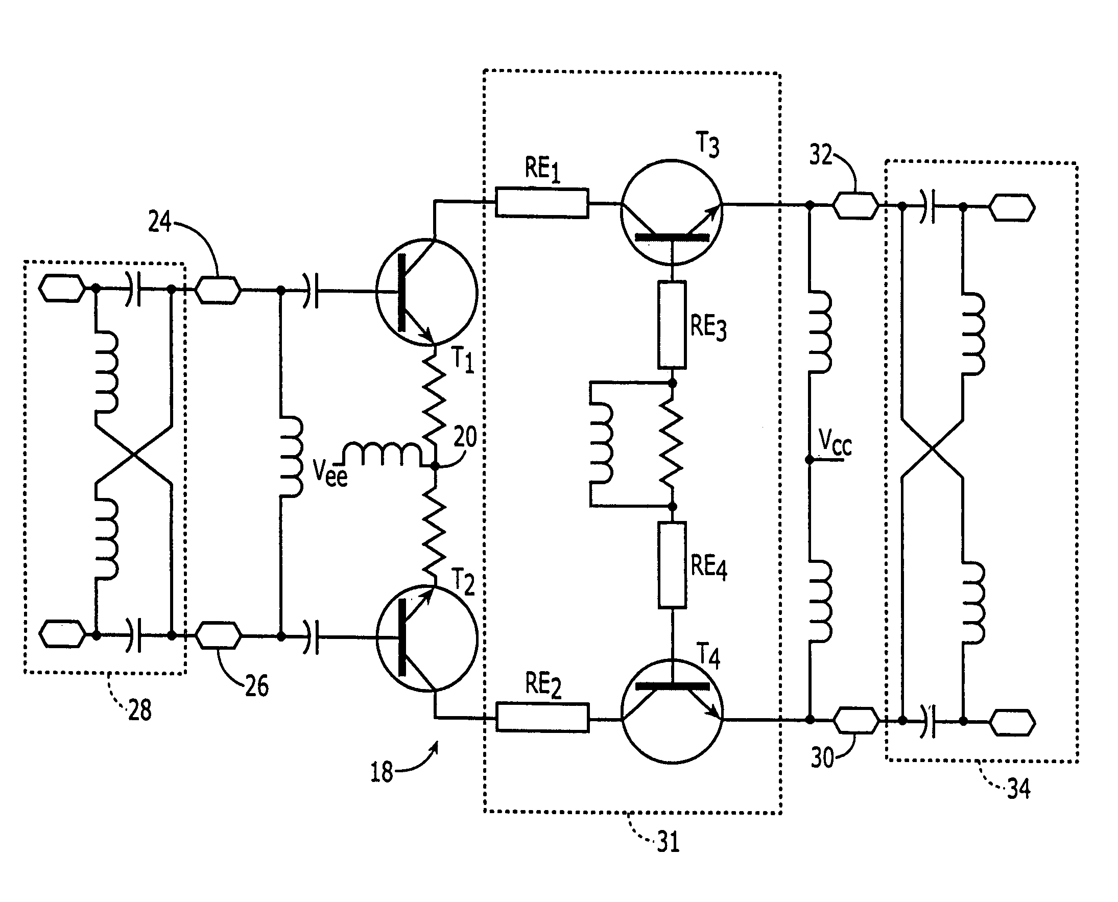
[0012]The present invention provides a method and apparatus for obtaining power amplification at high frequencies (1–100 GHz) using Silicon-Germanium (SiGe) transistors.

[0013]SiGe devices consist of thin layers of Ge grown over Si. Because of the 4% difference in lattice structures, the resultant combination has lattices that are strained, allowing material parameters such as the band gap to be varied. In particular, the strained Si has increased carrier mobility (2–3 time greater than Si), allowing faster switching-speed transistors to be fabricated. The increased switching-speed, however, comes at the cost of reduced break down voltage of the devices. In a class A power amplifier, the power output is proportional to the product of the current and the voltage, i.e., power=Vrms·Irms / 2. The reduced break down voltage, therefore, significantly reduces the maximum power that can be output from an amplifier using SiGe transistors.

[0014]SiGe amplifiers exhibit a further reduction in powe...


PUM


Abstract

A high-power, high frequency (1–100 GHz) power amplifier, made using SiGe transistors. A differential common-emitter amplifier section supplies the voltage amplification, allowing the total voltage swing of the amplifier to be twice the breakdown voltage of the individual transistors. Current amplification is supplied by a differential common-emitter amplifier section, connected in cascode with the differential common-emitter amplifier section. Appropriately chosen resonators in the cascode connection resonate out the Miller effect, negative current feed back of the circuit at the amplifier's operational frequency, allowing the amplifier to provide high power output at the operational frequency.

Description

FIELD OF THE INVENTION[0001]The present invention relates to power amplifiers, and more particularly to high frequency SiGe power amplifiers.BACKGROUND OF THE INVENTION[0002]Silicon-Germanium (SiGe) transistors are high-speed, low cost transistors. They are produced by growing a thin, epitaxial layer of Ge on a Si substrate. Because of the 4% difference in size between the Si and Ge lattice structures, the Si lattice near the surface of the Si substrate is strained, allowing material parameters such as the band gap to be varied. In particular the strained Si has increased carrier mobility (2–3 time greater than Si), allowing faster switching-speed transistors to be fabricated. Moreover, because the Ge is a thin, epitaxial layer, standard Si fabrication technology can be used, resulting in low costs and providing compatibility with conventional CMOS technology.[0003]The high speed switching of SiGe bipolar transistors, however, comes at the cost of reduced transistor breakdown voltag...

Claims


Application Information

Patent Timeline
Patent Type & Authority Patents(United States)
IPC IPC(8): H03F3/45
CPCH03F3/191H03F3/45089H03F3/604H03F2200/153H03F2203/45638H03F2203/45644
Inventor HELMS, DAVID RICHARDPOINT, JR., ROBERT WARRANT
Owner COBHAM DEFENSE ELECTRONICS SYST CORP
Why Eureka
Try Eureka