
Fluid dynamic bearing with non-linear damping

a fluid dynamic bearing and non-linear technology, applied in sliding contact bearings, electrical-based machining electrodes, instruments, etc., can solve the problems of non-linear stiffness and damping of an fdb with respect to the change in bearing gap subject to motion, and achieve the effect of stable flying heigh

Inactive Publication Date: 2007-03-20
SEAGATE TECH LLC
View PDF15 Cites 9 Cited by
  • Summary
  • Abstract
  • Description
  • Claims
  • Application Information

AI Technical Summary

Benefits of technology

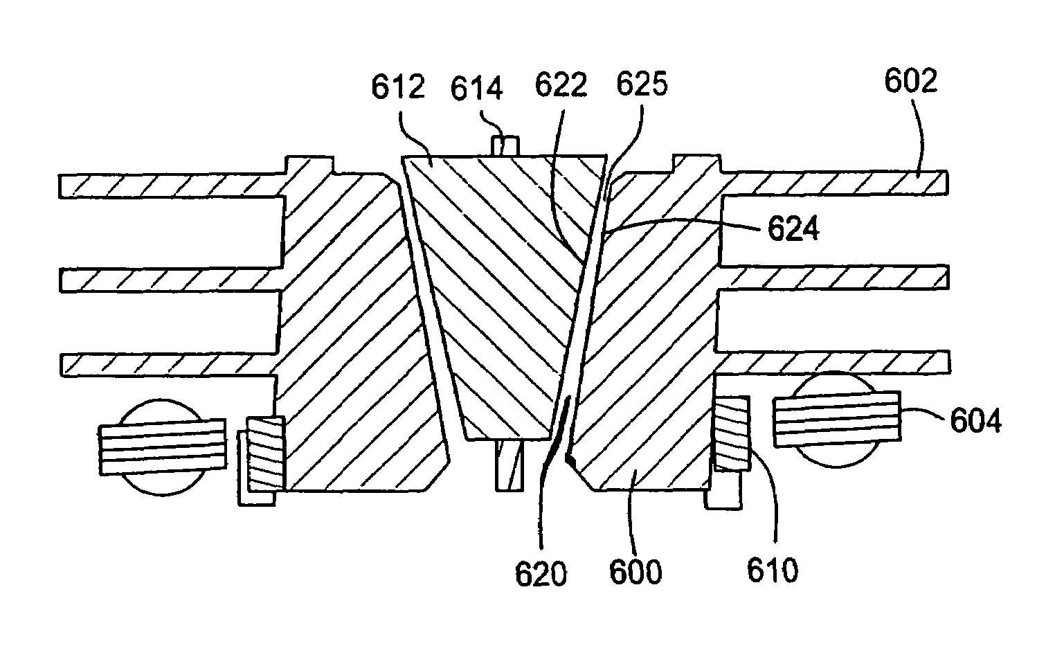
[0013]In a linear system the spectral content of action and reaction are identical, i.e. a motion at one frequency will result in a force at the same frequency and vice-versa. However, stiffness and damping of an FDB are non-linear with respect to the change in bearing gap subject to motion. The principle of this invention is to define ways to make use of the non-linearity in the bearing system to create a reaction richer in spectral content and in more degrees of freedom than the action which is the source of the disturbance of the spindle and bearing assembly. This principle allows us to spread the dissipation of the disturbing energy over a wider bandwidth and into axes of movements that do not diminish the recording accuracy of the disc drive.
[0022]In one preferred example, the shaft includes upper and lower conical bearings having effective surfaces and gaps of different sizes. Further, the larger bearing surface with narrower gap, will use air or gas. Alternatively, the cones may be replaced with combinations of thrust and journal bearings or even spherical bearings, provided the difference in dynamic stiff, or sensitivity of axial load to gap change. In other words, the invention takes advantage of the fact that if the shaft moves axially and one gap is larger than the other then the impact of that change will be smaller on the load on the shaft.

Problems solved by technology

However, stiffness and damping of an FDB are non-linear with respect to the change in bearing gap subject to motion.

Method used


Image

  • Fluid dynamic bearing with non-linear damping
  • Fluid dynamic bearing with non-linear damping
  • Fluid dynamic bearing with non-linear damping

Examples


example 1

[0053]Referred to FIGS. 5A and 5B, preferably the top surface 570 of thrust plate 516 would be grooved to establish a thrust plate. Also a journal bearing 580 would be defined in the gap 582 between the shaft 510 and the sleeve 512 typically comprising 2 grooved regions 531, 532 which can be defined on either surface. Finally, the surface 538 of the disc 540 is close enough to the facing surface 541 of sleeve 512 to establish the other critical gap 550 which works with bearing 516 to accomplish the damping. Note that neither of the surfaces 538, 541 facing gap 550 needs to be grooved to support the rotating system. Preferably in this design the gap 550 is air, and the gap 526 is liquid filled.

example 2

[0054]Referring to FIG. 4, preferably 3 bearing surfaces could be established by providing grooves on a surface of thrust plate 420 to establish a thrust bearing in the gap between 420 and 422; and further providing journal bearings comprising grooved regions on the surface of the shaft 414 or sleeve 410. The surface 432 of sphere 418 (and the facing surface of sleeve 410) are left ungrooved. Alternatively, grease is placed in the gap 440 (which is thick enough to stay in place).

example 3

[0055]Referring to FIG. 7, this shows a shaft 700 with a thrust plate 710 at one end, having a relatively large gap 720 with the surrounding sleeve. The shaft supports a disc 730 for rotation over a surface 740 of a stationary hub or sleeve 750. Using the invention, air in the small gap 760 would work with liquid in journal bearings 770, 772 and thrust bearing 774 to damping out effects of tilting. The design would utilize a single head, leaving the lower surface 780 of the disc available for damping.


PUM

PropertyMeasurementUnit
frequencyaaaaaaaaaa
frequenciesaaaaaaaaaa
speedsaaaaaaaaaa

Abstract

Thus, if a shock or other disturbance to the system occurs that tilts the bearing assembly, the resulting motion is both a tilting, and a motion which is axial. If a shock axially moves the hub assembly, only an axial motion occurs. Thus the system has a non-linear behavior. Pursuant to this invention, when a tilting disturbance occurs, and some of it is dissipated in a net axial movement at a different frequency, energy is subtracted out of the system with motion that is not linearly related to the disturbance was that created it.

Description

CROSS REFERENCE TO A RELATED APPLICATION[0001]This application claims priority to provisional application Ser. No. 60 / 378,876, filed May 7, 2002, entitled FDB with Non-Linear Damper filed by Hans Leuthold et al on May 7, 2002, and to provisional application Ser. No. 60 / 383,820, filed May 28, 2002, entitled Grooving Technique For Reduced Power Consumption filed by Gunther Heine et al on May 28, 2002 both of which are incorporated herein in their entirety by reference.FIELD OF THE INVENTION[0002]The present invention is directed to the field of disc drives incorporating fluid dynamic bearings, and more particularly to damping undesirable responses to excitation of the drive or bearing system.BACKGROUND OF THE INVENTION[0003]Disc drive memory systems have been used in computers for many years for storage of digital information. Information is recorded on concentric tracks of a magnetic disc medium, the actual information being stored in the forward magnetic transitions within the mediu...

Claims


Application Information

Patent Timeline
Patent Type & Authority Patents(United States)
IPC IPC(8): G11B17/02F16C17/10G11B25/04B23H3/04B23H9/00F16C17/26F16C33/10G11B19/20
CPCB23H3/04B23H9/00F16C17/045F16C17/102F16C17/105F16C41/008F16C33/107G11B19/2018F16C32/06G11B33/00F16C17/26F16C2370/12
Inventor LEUTHOLD, HANSIMMISCH, SUSANCEBALLOS, SAULTILLER, MICHAEL
Owner SEAGATE TECH LLC
Learn More