
Polishing apparatus

a technology of polishing apparatus and rotary disc, which is applied in the direction of grinding drives, grinding drives, manufacturing tools, etc., can solve the problems of inability to quantitatively determine when the initialization process of the polishing pad is completed, and the method is not employed to detect the initialization completion

Inactive Publication Date: 2007-03-13
EBARA CORP
View PDF11 Cites 11 Cited by
  • Summary
  • Abstract
  • Description
  • Claims
  • Application Information

AI Technical Summary

Benefits of technology

"The present invention provides a polishing apparatus and method that can quantitatively detect the completion of the initialization process of a polishing pad. This is accomplished by using a current sensor to detect the drive current supplied to the polishing table and workpiece holder, which is increased when the polishing pad comes into contact with a dummy workpiece and is reduced when the protective layer on the polishing pad is removed. The detected drive current is compared with a predetermined threshold to determine when the polishing pad is ready for polishing. This allows for improved efficiency and prevents wear and tear on the polishing pad."

Problems solved by technology

Accordingly, it is impossible to quantitatively determine when the initialization process of the polishing pad is completed.
Although there has been known a method of detecting an endpoint of a polishing process of a semiconductor wafer, such a method is not employed to detect completion of an initialization process of a polishing pad.

Method used


Image

  • Polishing apparatus
  • Polishing apparatus
  • Polishing apparatus

Examples


Embodiment Construction

[0026]A polishing apparatus according to an embodiment of the present invention will be described below with reference to FIGS. 1 through 5. Like or corresponding parts are denoted by like or corresponding reference numerals throughout drawings, and will not be described below repetitively.

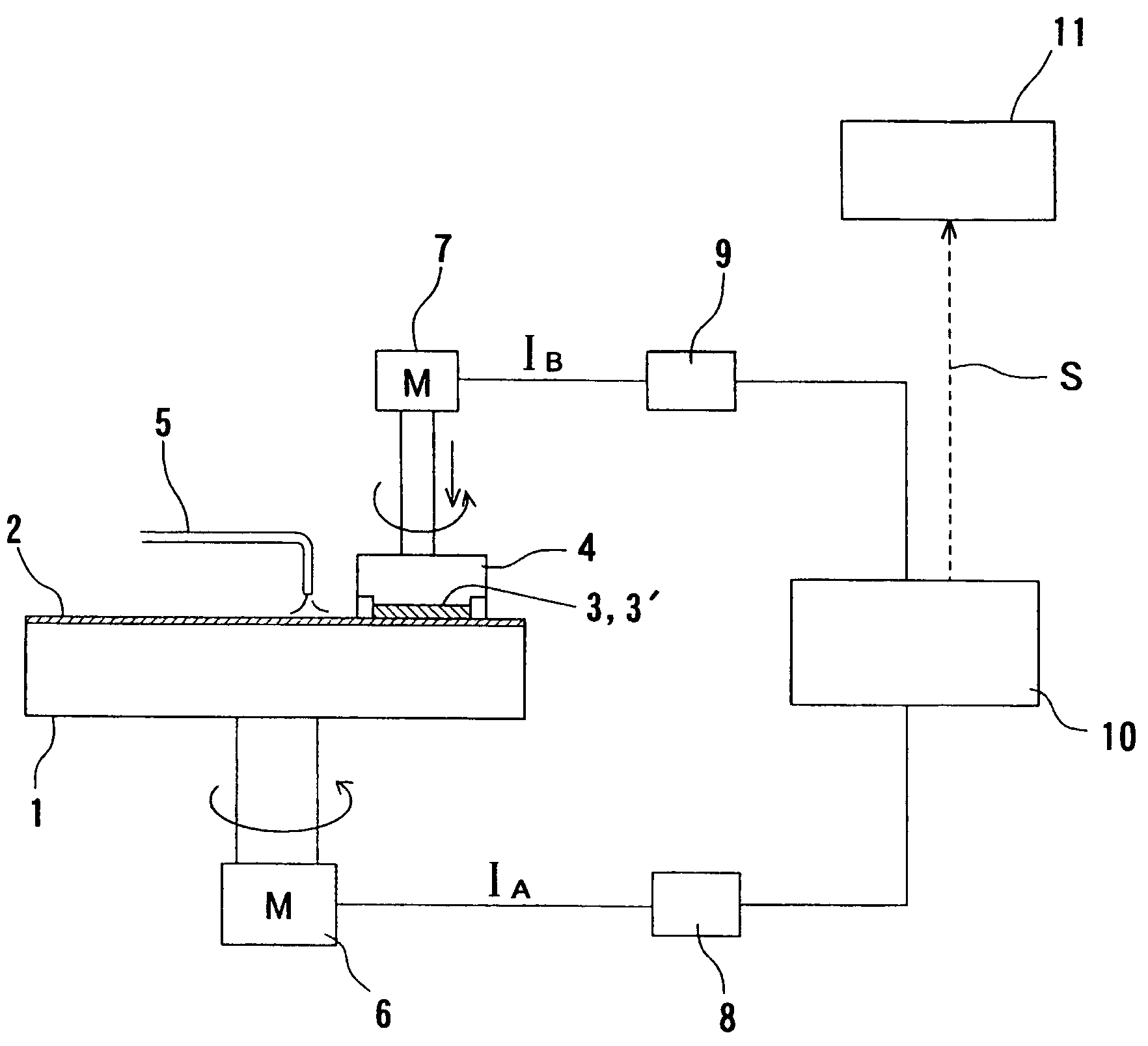
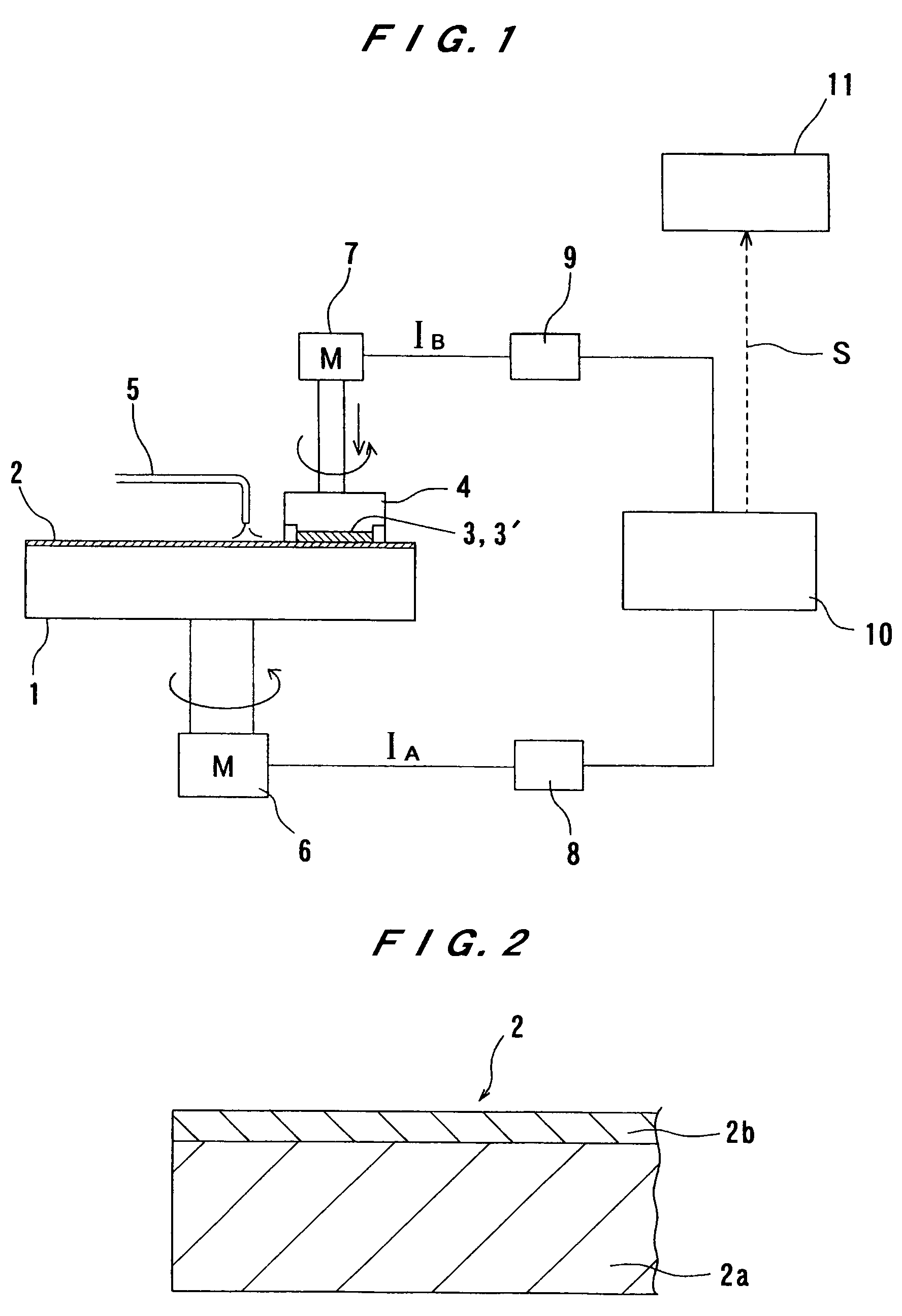
[0027]FIG. 1 is a schematic view showing a polishing apparatus according to an embodiment of the present invention. As shown in FIG. 1, the polishing apparatus has a polishing table 1 having a polishing pad 2 attached to an upper surface thereof, a polishing table motor 6 for rotating the polishing table 1, a top ring 4 for holding a substrate 3 such as an SOI wafer, a bare silicon wafer, or an oxide film wafer, a top ring motor 7 for rotating the top ring 4, and a polishing liquid supply nozzle 5 for supplying a polishing liquid (slurry) onto the polishing pad 2. Thus, the top ring 4 serves as a holder for bringing a surface of a workpiece into contact with the polishing pad 2 and pressing the wo...


PUM

PropertyMeasurementUnit
drive currentaaaaaaaaaa
flexibleaaaaaaaaaa
timeaaaaaaaaaa

Abstract

A polishing apparatus can detect completion of initialization of a polishing pad quantitatively. The polishing apparatus has a polishing table having a polishing pad attached thereto and a substrate holder configured to bring a surface of a substrate into contact with the polishing pad and press the substrate against the polishing pad. The polishing apparatus also has a drive mechanism operable to drive at least one of the polishing table and the substrate holder so as to provide a relative movement between the polishing pad and the substrate. The polishing apparatus includes a current sensor operable to detect a drive current supplied to the driving mechanism. The polishing apparatus also includes a polishing pad condition detector operable to detect a condition of the polishing pad based on the drive current detected by the current sensor when the dummy substrate is polished by a relative movement between the polishing pad and a dummy substrate held by the substrate holder.

Description

BACKGROUND OF THE INVENTION[0001]1. Field of the Invention[0002]The present invention relates to a polishing apparatus, and more particularly to a polishing apparatus for polishing a workpiece such as silicon on insulator (SOI), a bare silicon wafer, or an oxide film wafer. The present invention also relates to a method of detecting completion of an initialization process of a polishing pad attached to a polishing table.[0003]2. Description of the Related Art[0004]There has been developed a polishing apparatus for polishing a substrate such as an SOI wafer, a bare silicon wafer, or an oxide film wafer. Such a polishing apparatus includes a polishing table having a polishing pad, such as flexible polyurethane foam, attached to an upper surface of the polishing table, and a top ring for holding and rotating a substrate. The substrate, which is rotated by the top ring, is brought into contact with the polishing pad provided on the rotating polishing table and pressed against the polish...

Claims


Application Information

Patent Timeline
Patent Type & Authority Patents(United States)
IPC IPC(8): B24B49/00B24B1/00B24B51/00B24B49/10B24B53/007B24B53/017B24B53/02H01L21/304
CPCB24B53/017B24B49/10
Inventor ONO
Owner EBARA CORP
Learn More