
Brine maker

Active Publication Date: 2007-03-06
DUOELEVATOR MFG
View PDF20 Cites 31 Cited by
  • Summary
  • Abstract
  • Description
  • Claims
  • Application Information

AI Technical Summary

Benefits of technology

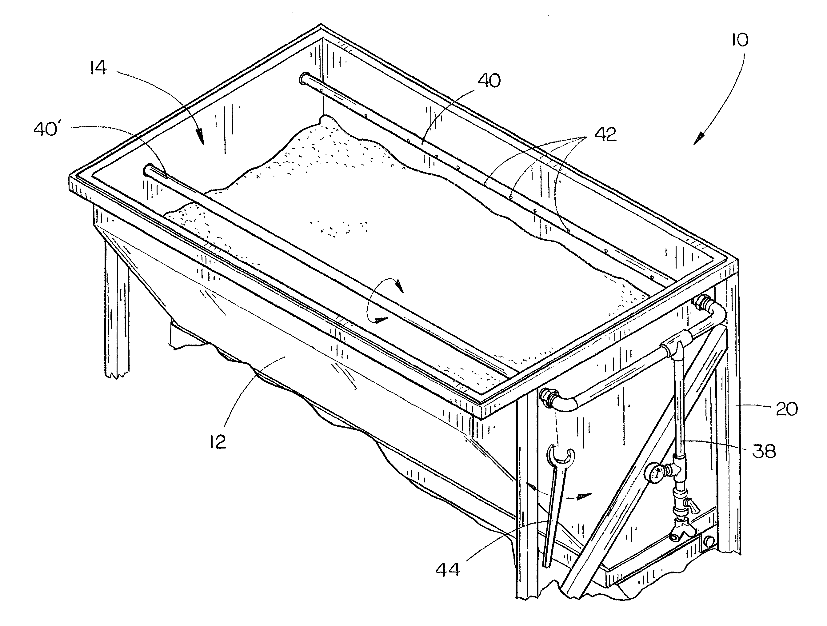
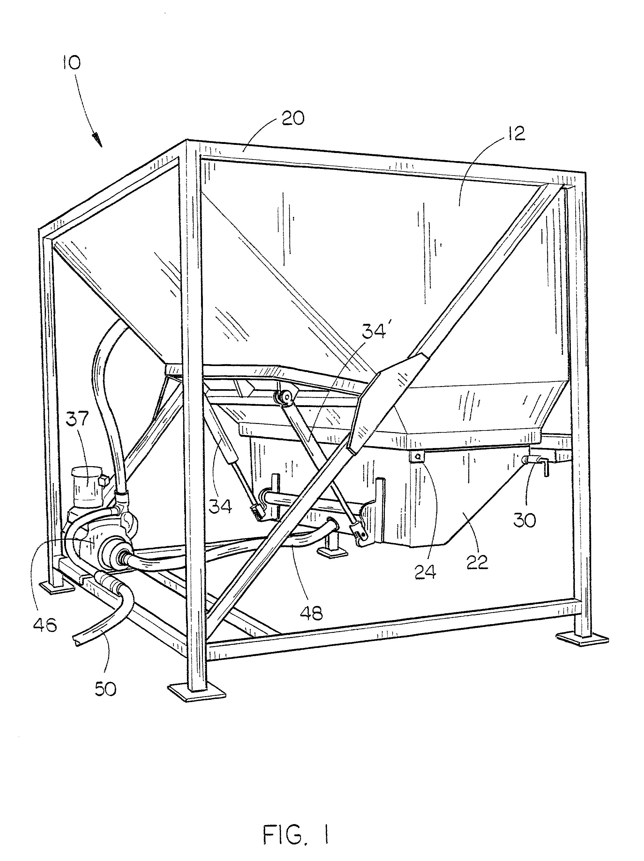
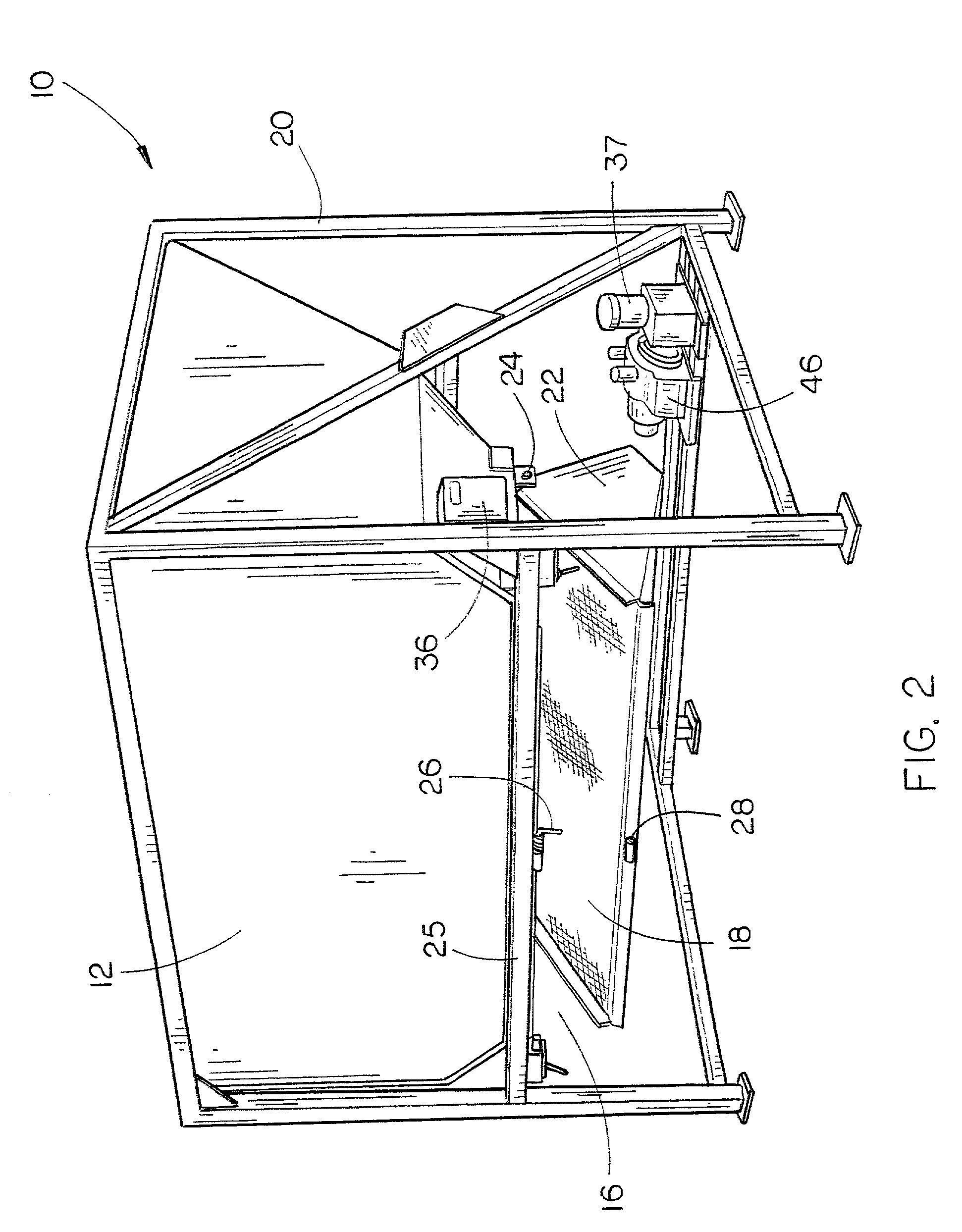
[0011]The brine maker of the present invention efficiently produces liquid compounds and is easy to clean and maintain. Salt is loaded into the salt hopper using a front end loader or similar machine. Fluid is provided to positionable spray bars, disposed within the salt hopper. As the fluid stream exits the spray bars and dissolves the salt, or other dissolvable material, it passes through a solids screen that filters unwanted particulate away from the “brine.” The brine temporarily collects in a receiving tank, positioned below the salt hopper and solids screen. The brine can then be pumped to remote storage tanks or pumped back into the salt hopper, via the spray bars, to increase the concentration of the brine.
[0012]The positionable spray bars are rotatably mounted within the salt hopper so that the operator can adjust the fluid spray as the volume of dissolvable material within the hopper changes. The spray bars have spray holes arranged along the length of the spray bars. The spacing between the holes, as well as their individual diameters, are varied to position the larger of the holes in close relation to one another in the middle of the spray bars. The smaller of the holes are spaced more distantly from one another and are located proximal the ends of the spray bars. This arrangement concentrates the fluid spray on the dissolvable material (due to the conical-shape that the material tends to take as it is dumped into the hopper) to increase the efficiency of the brine maker.
[0013]The improvements of the present invention allow for fast and simple cleaning and maintenance. When the brine maker has to be cleaned, the operator simply positions the bucket of a front end loader beneath the receiving tank. A second operator then selects a hydraulic control switch, which activates a self-contained hydraulic pump, and shifts the hydraulic control valve. This retracts a pair of hydraulic cylinders, which pivot the receiving tank and solids screen downward so that the debris, which was inside the upper salt hopper, falls into the loader bucket. The operator then simply reselects the hydraulic control switch to pivot the receiving tank upwards. The operator engages a solids screen retaining pin to hold the solids screen against the hopper and pivots the receiving tank back down again. In this position, the silt may be removed from the receiving tank with a hose and squeegee. With the bucket of the front end loader placed beneath the receiving tank, the silt can be simply dumped into the bucket for disposal.

Problems solved by technology

This basic brine maker design suffers from one key deficiency; clean-out is difficult and time-consuming.
The time and resources spent on cleaning the brine maker are costly and bothersome.
Many operators delay cleaning their brine makers because it takes too long and requires valuable resources.
However, when the brine makers are not regularly cleaned, the speed and efficiency of the brine production process is greatly reduced.
Clean-up at that point is made extremely difficult.
Accordingly, the operator must choose between the excessive time and work of cleaning the brine maker and reducing the speed and efficiency that they are capable of producing brine.
While this brine maker concept was an improvement over previous brine makers as far as clean-out is concerned, it still suffered from two key flaws.
First, the operator would have to disconnect the bucket from his front end loader before attaching the loader to the removable salt hopper.
This consumes a lot of time, especially when trying to align the loader pins with the salt hopper bucket.
Moreover, silt still collects in the brine hopper, and there is no easy way to clean the silt out.
If the silt is not cleaned out, suspended solids will collect in the brine storage tanks and silt will eventually clog the suction port that leads to the brine discharge pump.
First, the complexity of the design and hydraulics system increased the unit's costs and manufacturing time.
Second, the unit required a greater working area to pivot the salt hopper.
The pivoting salt hopper further complicated the engineering and maintenance of the fluid inlet lines.
Moreover, cleaning and maintenance of the salt screen and brine hopper were still somewhat cumbersome.
Therefore, the even horizontal spray effectively strikes the salt load in the center, but the sides of the spray are fired ineffectively into the opposite side of the salt hopper.

Method used


Image

  • Brine maker
  • Brine maker
  • Brine maker

Examples


Embodiment Construction

[0034]The system for producing liquid compositions of the present invention will be generally referred to as the brine maker 10. It will be understood by one of ordinary skill in the art that, while the brine maker 10 herein will be described as producing salt brine, a wide range of liquid compositions could be made using the present device with few, if any, modifications.

[0035]The brine maker 10 for producing salt brine, shown in FIGS. 1 through 6, 10, and 11, is generally provided with a salt hopper 12, having at least a first opening 14 for receiving soluble materials, such as rock salt, and a second opening 16 for the passage of the liquid composition through a solids screen 18, which forms the base of salt hopper 12. The salt hopper 12 is secured to a frame 20 adjacent the upper end thereof. A brine hopper, or receiving tank 22, having an open top and closed bottom, is operatively and pivotally coupled to salt hopper 12 at hinge 24. Accordingly, receiving tank 22 can be pivoted...


PUM

PropertyMeasurementUnit
Timeaaaaaaaaaa
Diameteraaaaaaaaaa
Solubility (mass)aaaaaaaaaa

Abstract

An improved brine maker includes a hopper having open upper and lower ends, a solids screen, and a receiving tank having an open upper end and closed lower end. The solids screen and receiving tank are pivotally secured to the hopper adjacent its lower end. The receiving tank and solids screen pivot freely and independently of the hopper to provide quick and easy access for cleaning and maintenance. Rotatable spray bars are positioned within the hopper to direct the dissolving fluid at the soluble material within the hopper. Spray holes having varying diameters and spaced relation to one another customize the fluid spray pattern for greater efficiency. A hydraulic assembly assists the operator throughout the cleaning and maintenance operations of the brine maker to reduce the time and manpower required.

Description

BACKGROUND OF THE INVENTION[0001]1. Field of the Invention[0002]This invention relates to devices for dissolving solid material into liquid and more particularly to a brine maker that can be efficiently operated, cleaned, and maintained.[0003]2. Description of the Prior Art[0004]Salt brine production systems, also known as brine makers, have been used for hundreds of years in many different industries and applications. For example, several state road departments spray liquids, including salt brine, onto road surfaces before winter storms. They also spray these liquids onto dry salt-sand mixtures just before the mixtures are spread onto the roadways. Both methods, if done properly, have proved to be successful in de-icing roads and preventing road surfaces from freezing in the first place.[0005]The general method for making salt brine has not changed over the years. In a downward flow brine maker, salt is loaded into a salt hopper, which is placed directly above a brine hopper. A sal...

Claims


Application Information

Patent Timeline
IPC IPC(8): B01D11/02
CPCB01F1/0022B01F15/00922B01F15/00785Y10S422/902B01F21/20B01F35/451B01F35/10
Inventor HELLBUSCH, JAMES A.PLUGGE, DALE L.
Owner DUOELEVATOR MFG
Learn More