Passive broadband infrared optical limiter device based on a micro-optomechanical cantilever array

a micro-optomechanical and cantilever array technology, applied in the field of infrared optical limiters, can solve the problems of high incident fluence threshold, optical limit behavior begins, and there are no known rsa or multi-photon solutions that can be used in the mid ir and lwir regions

Inactive Publication Date: 2007-02-27
LOCKHEED MARTIN CORP
View PDF14 Cites 7 Cited by
  • Summary
  • Abstract
  • Description
  • Claims
  • Application Information

AI Technical Summary

Benefits of technology

[0008]The present invention relates to an infrared limiting device based on a micro-optomechanical cantilever array that is particularly well suited for limiting the radiation impinging upon a detector in the normal state, each microcantilever device in the array behaves likes a mirror to reflect the infrared radiation to the detector. The microcantilever device absorbs radiation outside the mid IR or LWIR region. When the radiation is stronger than a predetermined threshold, the microcantilever device bends as a result of thermo-mechanical forces, and it reflects the radiation away from the detector, thereby limiting the radiation impinging upon the detector. An advantage of the present system is that each pixel of the detector can be addressed individually, and the limiting is localized.

Problems solved by technology

The disadvantage of these materials as limiters includes a high incident fluence threshold which the optical limiting behavior begins.
More importantly, however, there are no known RSA or multi-photon solutions that can be used in the mid IR and LWIR regions.
The main function of this limiter is laser hardening, and it is a relatively narrowband device that is not suitable for handling a broadband of wavelengths.

Method used


Image

  • Passive broadband infrared optical limiter device based on a micro-optomechanical cantilever array
  • Passive broadband infrared optical limiter device based on a micro-optomechanical cantilever array
  • Passive broadband infrared optical limiter device based on a micro-optomechanical cantilever array

Examples


Embodiment Construction

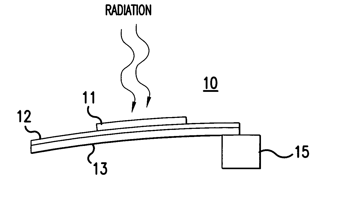
[0014]One of the goals of the present invention is to protect an infrared device such as a LWIR camera against damage from continuous wave (CW), broadband radiation, such as radiation from the sun. The present invention, however, is not limited to LWIR devices, and it is suitable for use with mid IR devices. Because of the high temperature and brightness, continuous wave radiation can be more harmful to the detector than a pulsed, narrow bandwidth laser. On the other hand, because of its high temperature, the continuous wave radiation has a hundred times more energy in the visible and near IR spectrum than in the mid IR or LWIR region. So the approach of this invention is to use the energy from visible and near IR region to operate the limiter in the LWIR or mid IR.

[0015]Referring now to FIG. 1, the main component of the infrared limiter of the present invention is a microfabricated cantilever 10 and a mirror 11. The microcantilever 10 includes strips 12, 13 of different materials t...


PUM


Abstract

An IR limiting device for a detector that is based on a micro-optomechanical cantilever array is disclosed. In the normal state, each microcantilever device in the array behaves like a mirror that reflects the infrared signal to the detector. The microcantilever device absorbs radiation outside the desired infrared region. When the radiation is stronger than a predetermined threshold, the microcantilever device bends as a result of thermo-mechanical forces, and it reflects the signal away from the detector, thereby limiting the radiation. The advantage of such a system is that each pixel in the detector can be addressed individually, and the limiting is localized.

Description

BACKGROUND OF THE INVENTION[0001]1. Field of the Invention[0002]The present invention relates to an infrared optical limiter, and more specifically, to a passive broadband infrared optical limiter device based on an array of micro-optomechanical cantilevers that bend as a result of thermo-mechanical forces.[0003]2. Description of the Related Art[0004]There is a need for a broadband passive infrared optical power limiting device. In the present application, the wavelengths of the infrared spectrum will be referred to as the mid wavelength IR (mid IR, wavelength 3 to 5 microns) region and the long wavelength infrared (LWIR, wavelength 7 to 14 microns) region. Such an infrared optical limiter would be useful for protecting light sensitive items, such as the human eye, a photodetector or a camera against unexpectedly strong illumination. An ideal optical limiter is transparent under low level illumination at the wavelength of interest, but “dark” under strong incident light power. The o...

Claims


Application Information

Patent Timeline
Patent Type & Authority Patents(United States)
IPC IPC(8): G02B26/08G01J5/00
CPCG01J1/0414G01J1/04G01J1/0204G01J2001/0276
Inventor DALAKOS, GEORGELORRAINE, PETERWU, PINGFANLAWRENCE, BRIANYENISCH, WILLIAM TAYLOR
Owner LOCKHEED MARTIN CORP
Why Eureka
Try Eureka