Machine for intraoperative radiation therapy

a technology for intraoperative radiation therapy and machines, applied in radiation therapy, chemical to radiation conversion, x-ray/gamma-ray/particle irradiation therapy, etc., can solve the problems of not producing statistically reliable data, imposing considerable investment in a therapy, and not being convenient to use x, etc., to achieve the effect of convenient movemen

Inactive Publication Date: 2010-11-04
S I T SORDINA IORT TECH
View PDF7 Cites 2 Cited by
  • Summary
  • Abstract
  • Description
  • Claims
  • Application Information

AI Technical Summary

Benefits of technology

[0048]It is therefore an object of the present invention to provide a machine for IORT which is easily movable and to be positioned.
[0049]It is still an object of the present invention to provide such a machine which makes possible, in a reliable, simple and efficient way, to radiate an electron beam drastically reducing the diffusion of X rays, accurately controlling and shielding environmental radiation.
[0050]It is a further object of the present invention to provide such a machine which makes possible to very precisely measure the radiation dose.
[0051]It is always object of the present invention to provide such a machine which is technologically simple to be realised.

Problems solved by technology

In fact, out of the institutions dedicated to research, it could not be proposed to invest considerable amounts of money for a therapy that, due to limited Figures, could not produce statistically reliable data.
For radiating a particular organ which is exposed due to the surgical opening, it is not convenient to use X rays which are commonly used for conventional radiotherapy; in fact these are highly penetrative and once aimed at the area to be treated they involve everything being along their aiming direction, distributing undesired radiation doses also to other organs which are thereby damaged.
Moreover, the electron beams, thanks to the reduced penetration, are easily shaped and transversely limited, being thereby possible to treat only parts to be radiated, reducing the morbidity induced by applications of considerable doses such as the ones used in IORT.
It is evident that an error in dosimetry in IORT may be much more dangerous than in classical radiotherapy.
In order to eliminate or at least minimise patient movement, some institutes have built surgical rooms next to or within the radiotherapy bunker; in any case these were extremely expensive solution which have in fact limited the diffusion of IORT.
First of all, as it has been already observed, they do not satisfy the requirement for mobility, also because the apparatus is heavy and bulky.
This implies a complex and difficult logistic organisation, since the above is a procedure which is extraneous to the normal conduct of a surgical operation, and a time extension of the anesthesia, further causing a physical stress for the patient.
However, the time of real use is greatly shorter, since the radiation lasts about one minute and the whole operation of positioning and subsequent removal of the patient does not generally reach 15 minutes.
Hence, this results in keeping mostly unused a machine potentially capable of treating an high number of patients.
Although some mobile machines for radiotherapy have been developed, these have drawbacks due to weight and size and to the need of calibration after movements.
Moreover, a machine, either immobile or mobile, is driven onto the patient to be radiated by a radiotherapy technician skilled in driving, who is, however, not sterile, since he has to handle objects, such as the remote control, which cannot be sterilised.
This procedure is quite dangerous, because the one driving the machine has a very limited sight of the operating zone and there is the risk of hitting or compressing internal organs of the patient which are quite fragile.
Further drawbacks of the known machines for radiotherapy are due to the system for diffusing the electron beam.
However, such beam flattening solution is inadequate for machines for Intraoperative Radiotherapy, since the diffusing plate 10 produces a significant quantity of braking X rays which permeate the surgical room environment and are difficult to be shielded.
This imposes a noticeable shielding which causes high values of the machine weight, making the use of special floors be necessary.
However, the warning and control procedures are not completely accurate.
The braking X radiations are the most harmful and inevitable.
However, while in the case of immobile machines for radiotherapy the absorbing mass 13 is oriented in fixed position with respect to the accelerator axis, in the case of mobile machines for radiotherapy the correct positioning of the absorbing mass 13 is not simple, taking also into account the accuracy imposed by the law for the safety of the operators.
A further drawback present in known machines for radiotherapy is due to the system for measuring the beam, needed in all the accelerators for radiotherapy in order to determine that the prescribed dose quantity has been really delivered by the machine and to stop delivering.
Since the typical flow of a mobile machine for Intraoperative Radiotherapy is of the order of 20,000 Gy / sec, the ionization chambers operate in a very low sensitivity region that does not allow them to appreciate variations lower than some point percent.
Considering that the precision limit of clinical dosimetry is of the order of 2%, it is evident that the transmission ionization chambers are unusable.
However, such a solution implies a very high environmental radiation quantity which imposes the use of a circular attenuator (a sort of collimator for the diffusion) in heavy material (depleted uranium).
The use of such a shielding causes the radiating head to be heavy and, due to balancing reasons, this propagates in cascade on the weights of the whole machine.
A further drawback of the known machines for radiotherapy is due to the accelerating structure.
However, the presence of tuning screws 18 creates a significant technological difficulty as far as the vacuum level is concerned.
This involves the necessity to heat the whole structure up to temperatures of the order of 500-600° C. These thermal cycles, besides being expensive, since they conspicuously extend the production time of the accelerator, also tend to make the building material get relaxed and, hence, to vary its physical size impairing the precision of tuning.

Method used


Image

  • Machine for intraoperative radiation therapy
  • Machine for intraoperative radiation therapy
  • Machine for intraoperative radiation therapy

Examples


Embodiment Construction

[0112]In the following of the description same references will be used to indicate alike elements in the Figures.

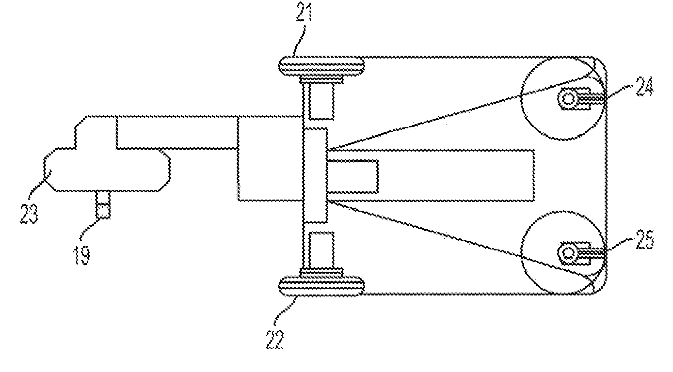
[0113]The machine for IORT according to the invention has a considerable mobility. In particular, the preferred embodiment has a weight lower than 400 Kg, eliminating any problem in floor statics and, most of all, in capacity of elevators and vehicles; moreover, it has reduced sizes, having a width of 80 cm, in order to make possible the movement through the elevator doors, and a length not larger than 2 metres; still, the turning radius is such to allow the machine to rotate around a vertical axis placed within the same machine; finally, the preferred embodiment of the machine is provided with autonomy of movement so that it can move without necessity to be supplied during transfer.

[0114]The machine for IORT according to the invention allows a sterile person, for example the radiotherapist, to directly control movement. This mobility can be obtained with a “sterile handl...


PUM


Abstract

Machine for intraoperative radiation therapy or IORT (Intra Operative Radio Therapy), comprising a body, a radiating head (23) connected to the body, and a shield for X rays. The shield comprises a mobile stand (29) supporting an absorbing mass (13), which is coupled, through connecting means (32), to means (33) for detecting the position of the absorbing mass (13), apt to give to a processor at least a signal indicating the position of the absorbing mass (13) with respect to the body of the machine. The processor determines, on the basis of the position and / or the orientation of the radiating head (23), the position of the absorbing mass (13) with respect to the electron beam axis.

Description

RELATED APPLICATIONS[0001]This Application is a divisional Application of U.S. application Ser. No. 10 / 515,991, filed Jul. 20, 2005, entitled “MACHINE FOR INTRAOPERATIVE RADIATION THERAPY”, which is a U.S. National Stage of PCT / IT03 / 00336 filed on May 29, 2003, which claims priority to Italian application RM2002A000301 filed on May 31, 2002, the disclosures of which are specifically incorporated herein in their entireties by specific reference thereto.FIELD OF THE INVENTION[0002]The present invention concerns a machine for intraoperative radiation therapy or IORT (Intra Operative Radio Therapy) which is easily movable, having reduced weight and size, and which makes possible, in a reliable, simple and efficient way, to radiate an electron beam drastically reducing the diffusion of X rays, accurately controlling environmental radiation, and very precisely measuring the radiation dose.[0003]It is known that Intraoperative Radiotherapy consists in treating the patient with ionising rad...

Claims


Application Information

Patent Timeline
Patent Type & Authority Applications(United States)
IPC IPC(8): A61N5/10
CPCA61N5/10A61N2005/1089A61N5/1048A61N2005/1094
Inventor FANTINI, MARIOIACOBONI, VINCENZOGAVA, AQUILINO
Owner S I T SORDINA IORT TECH
Why Eureka
Try Eureka