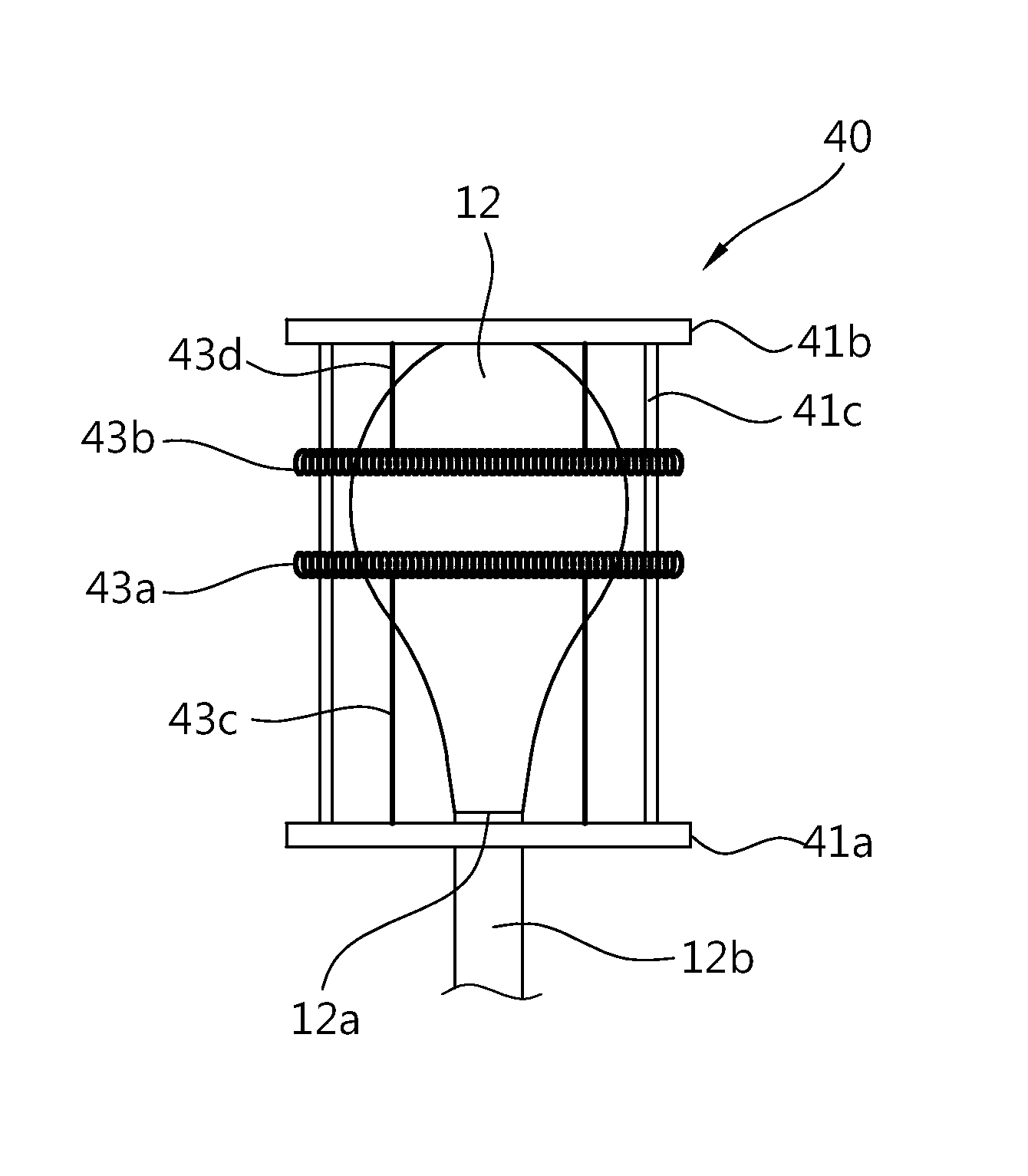
Electrode for high-frequency surgery and high-frequency surgery device
a high-frequency surgery and electrode needle technology, applied in the field of electrodes for radiofrequency surgery, can solve the problems of affecting affecting the treatment effect, so as to achieve the effect of improving the reliability of surgery, convenient insertion and movement inside, and efficient us
- Summary
- Abstract
- Description
- Claims
- Application Information
AI Technical Summary
Benefits of technology
Problems solved by technology
Method used
Image
Examples
first exemplary embodiment
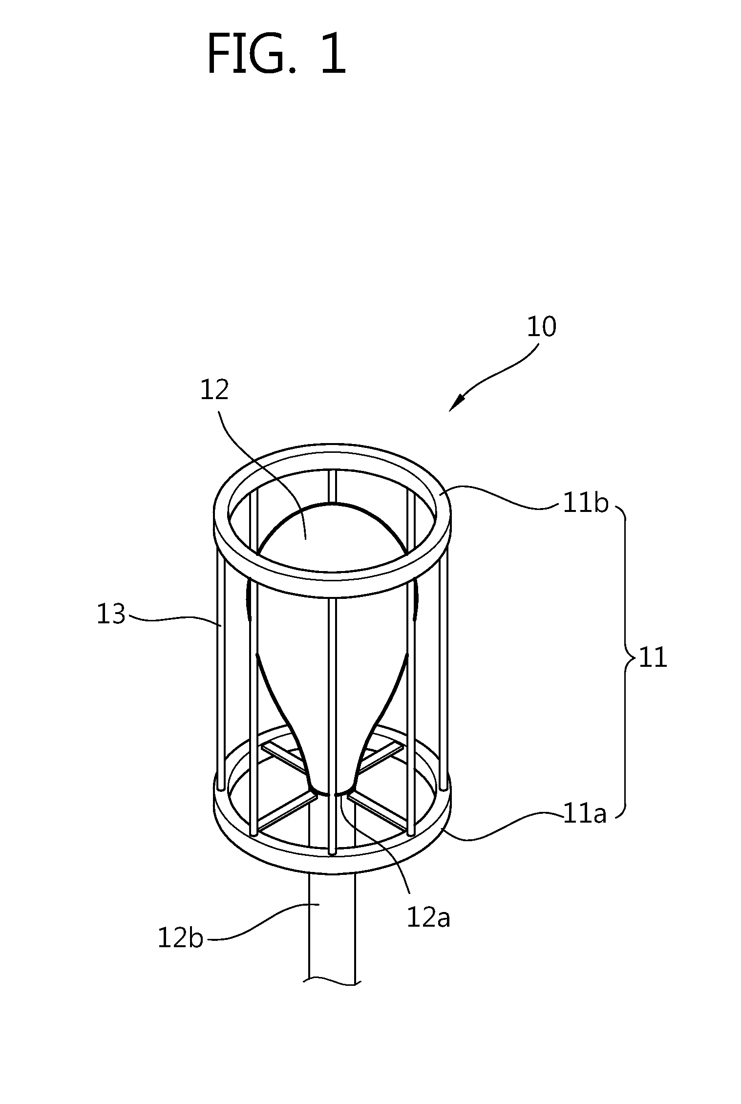
[0035]FIG. 1 is a diagram illustrating an electrode for radiofrequency surgery according to a first exemplary embodiment.
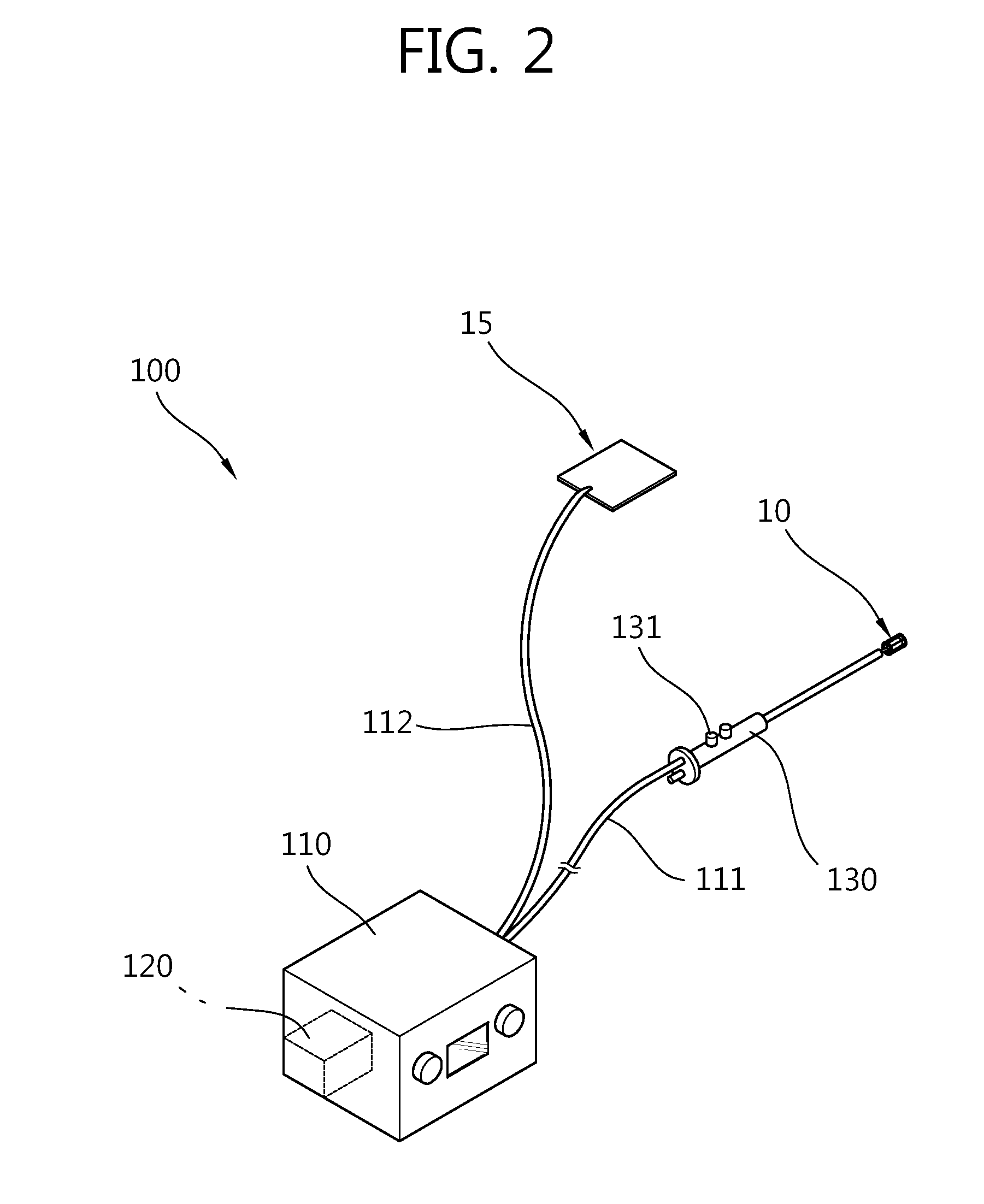
[0036]Referring to FIG. 1, an electrode 10 for radiofrequency surgery according to a first exemplary embodiment (hereinafter, referred to as an ‘electrode for radiofrequency surgery’) includes a supporter 11, a balloon 12, and a conductor.
[0037]The supporter 11 may be divided into a first support ring 11a and a second support ring 11b. The first support ring 11a and the second support ring 11b are spaced apart from each other with the balloon 12 therebetween. A gas inlet 12a into which gas may be injected is formed in the balloon 12. A gas supply pipe 12b may be coupled with the gas inlet 12a. The gas supply pipe 12b is coupled with the first support ring 11a. The gas inlet 12a is coupled with the gas supply pipe 12b, and as a result, the balloon 12 may be supported to the first support ring 11a. Accordingly, the balloon 12 may be moved together with the first sup...
second exemplary embodiment
[0055]FIG. 5 is a diagram illustrating an electrode for radiofrequency surgery according to a second exemplary embodiment, and FIG. 6 is a diagram schematically illustrating a configuration of a radiofrequency surgery device according to the second exemplary embodiment.
[0056]Referring to FIGS. 5 and 6, some of a plurality of wires 23 may be constituted by positive wires 23a, and the rest of the plurality of wires 23 may be constituted by negative wires 23b. In this case, a first support ring 21a and a second support ring 21b are made of non-conductive materials so as to block the positive wires 23a and the negative wires 23b from being electrically connected to each other.
[0057]In addition, a radiofrequency generator 210 is connected to an electrode 20 for radiofrequency surgery by a single cable 211. A positive power supply line connected to the positive wires 23a and a negative power supply line connected to the negative wires 23b may be embedded inside the signal cable 211. In th...
third exemplary embodiment
[0060]FIG. 7 is a diagram illustrating an electrode for radiofrequency surgery according to a third exemplary embodiment.
[0061]Referring to FIG. 7, in an electrode 30 for radiofrequency surgery according to a third exemplary embodiment, a plurality of coil springs 33 may be used as a conductor.
[0062]One end of the plurality of coil springs 33 is coupled with a first support ring 31a, and the other end thereof may be coupled with a second support ring 31b. The plurality of coil springs 33 is arranged to cover the outside of the balloon 12. Accordingly, the shape of the plurality of coil springs 33 may be deformed according to the volume of the balloon 12. That is, the plurality of coil springs 33 maintains a linear shape connecting the first support ring 31a and the second support ring 31b, and may be deformed in an outwardly convex shape while the volume of the balloon 12 is expanded.
[0063]In this case, the plurality of coil springs 33 may be implemented to have the same polarity, a...
PUM
 Abstract
Description
Claims
Application Information
 - R&D
- Intellectual Property
- Life Sciences
- Materials
- Tech Scout
- Unparalleled Data Quality
- Higher Quality Content
- 60% Fewer Hallucinations
Browse by: Latest US Patents, China's latest patents, Technical Efficacy Thesaurus, Application Domain, Technology Topic, Popular Technical Reports.
© 2025 PatSnap. All rights reserved.Legal|Privacy policy|Modern Slavery Act Transparency Statement|Sitemap|About US| Contact US: help@patsnap.com


