Relay device

a relay and core technology, applied in relays, battery/cell propulsion, transportation and packaging, etc., can solve the problems of moving iron core and magnetic metal noise abnormality

Pending Publication Date: 2022-02-24
TOYOTA JIDOSHA KK
View PDF4 Cites 0 Cited by
  • Summary
  • Abstract
  • Description
  • Claims
  • Application Information

AI Technical Summary

Benefits of technology

[0014]In the relay device, even when a ripple current flows through the first portion and the second portion, the ripple current flows through the first portion and the second portion in the opposite directions. The first portion and the second portion are disposed to be opposed to each other. Thus, an electromagnetic field formed by the ripple current flowing through the first portion and an electromagnetic field formed by the ripple current flowing through the second portion attenuate each other. This can restrict the radiation of the electromagnetic field from the relay device.

Problems solved by technology

When the moving iron core and the metallic members therearound are exposed to the high-frequency electromagnetic field, the moving iron core and magnetic metals vibrate, causing abnormal noise from the moving iron core and the magnetic metals.

Method used


Image

  • Relay device
  • Relay device
  • Relay device

Examples


example 1

[0067]FIG. 6 shows results obtained in various types of junction boxes 2A, 2B, 2C by examining abnormal noise that occurs from junction boxes 2A, 2B, 2C. The vertical axis of FIG. 6 indicates sound pressures (dB(A)) of abnormal noise that occurs from each of junction boxes 2A, 2B, 2C. Schematic configurations of junction boxes 2A, 2B, 2C will be described.

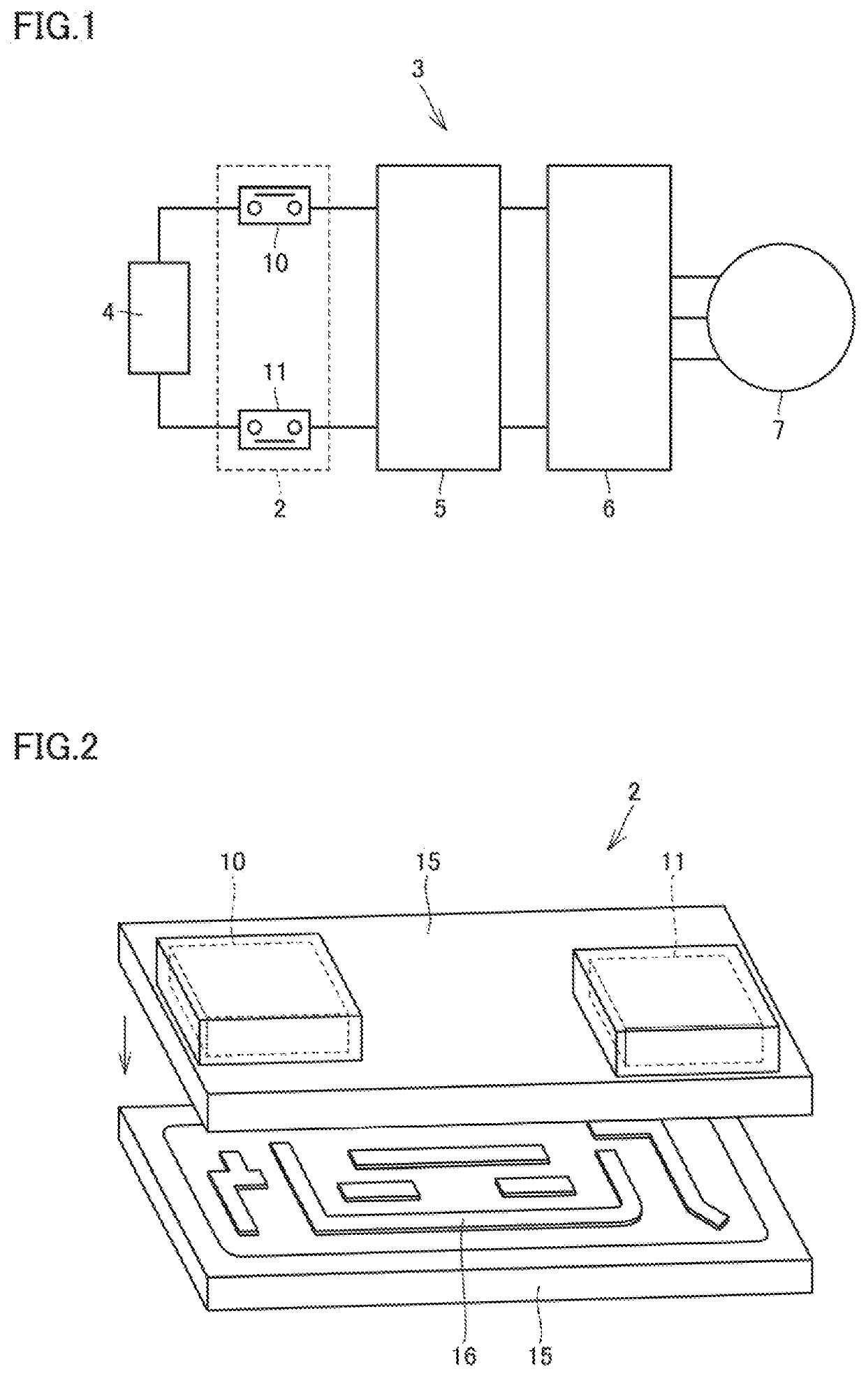
[0068]Junction box 2A includes a movable terminal 22A shown in FIG. 7 in place of movable terminal 22 of junction box 2 of the present embodiment. Note that bus bar 16 shown in FIG. 2 is not bonded to housing case 15 in junction box 2A.

[0069]Junction box 2B includes a connecting portion 58 shown in FIG. 8 in place of movable terminal 22 of junction box 2 of the present embodiment. Note that bus bar 16 shown in FIG. 2 is not bonded to housing case 15 in junction box 2B.

[0070]Junction box 2C includes connecting portion 58 shown in FIG. 8 in place of movable terminal 22 of junction box 2 of the present embodiment. Note that bus bar 16...

example 2

[0089]FIG. 9 schematically shows an experiment system 60 in which an inter-wire distance and an amount of radiation of an electromagnetic field are visualized. FIG. 10 is a sectional view of experiment system 60.

[0090]Experiment system 60 includes a wiring harness 61, a wiring harness 62, an iron plate (magnetic body) 63, and a microphone 64.

[0091]Wiring harness 61 and wiring harness 62 are disposed in parallel with each other. Stainless steel plate 63 is spaced from and above wiring harnesses 61, 62. Stainless steel plate 63 is positioned 10 mm above wiring harnesses 61, 62. Microphone 64 is disposed above stainless steel plate 63. Microphone 64 is disposed 400 mm above wiring harnesses 61, 62.

[0092]Wiring harnesses 61, 62 are connected to an AC source (not shown), and an AC current flows through wiring harnesses 61, 62.

[0093]The AC current flowing through wiring harness 61 and the AC current flowing through wiring harness 62 are 180° out of phase. Thus, a direction of a current D1...


PUM


Abstract

A relay device includes a positive terminal, a negative terminal spaced from the positive terminal, and a movable terminal that moves between a connection position and a distant position, the connection position being a position at which the movable terminal connects the positive terminal to the negative terminal, the distant position being a position at which the movable terminal is distant from the positive terminal and the negative terminal. The movable terminal includes a first contact portion connected to the positive terminal, a first portion extending away from the first contact portion, a second contact portion connected to the negative terminal, a second portion extending away from the second contact portion, and a connecting portion connecting the first portion to the second portion. The first portion and the second portion are disposed to be opposed to each other.

Description

[0001]This nonprovisional application is based on Japanese Patent Application No. 2020-139232 filed on Aug. 20, 2020 with the Japan Patent Office, the entire contents of which are hereby incorporated by reference.BACKGROUNDField[0002]The present disclosure relates to a relay device.Description of the Background Art[0003]A relay device has conventionally been known that is mounted in a hybrid system or the like. For example, a relay device disclosed in Japanese Patent Laying-Open No. 2017-175675 includes a positive fixed terminal, a negative fixed terminal, and a moving iron core.[0004]The moving iron core is provided to move between a position at which the moving iron core is in contact with the positive fixed terminal and the negative fixed terminal and a position at which the moving iron core is distant from the positive fixed terminal and the negative fixed terminal.[0005]As the moving iron core contacts the positive fixed terminal and the negative fixed terminal, the positive fi...

Claims


Application Information

Patent Timeline
Patent Type & Authority Applications(United States)
IPC IPC(8): H01H45/14H01H45/04
CPCH01H45/14H01H45/04H01H50/14H01H50/546H01H50/10B60L53/20B60L2270/142B60L50/60Y02T10/70Y02T10/7072Y02T90/14
Inventor NONOMURA, MITSUGU
Owner TOYOTA JIDOSHA KK
Why Eureka
Try Eureka