Portable apparatus for generating an induced low-frequency sinusoidal electric current

a low-frequency sinusoidal electric current and portable technology, applied in the field of portable devices, can solve the problems of high harmonic distortion rate, the level of the center of the apparatus that cannot the amperage of the electric current induced at the level of the apparatus does not exceed the threshold necessary, so as to increase the magnetic field source, reduce the charge, and increase the magnetic field

Active Publication Date: 2022-08-02
G C TECH
View PDF37 Cites 0 Cited by
  • Summary
  • Abstract
  • Description
  • Claims
  • Application Information

AI Technical Summary

Benefits of technology

[0009]The present invention therefore has the main goal of overcoming such drawbacks by proposing an apparatus that makes it possible to generate an induced low-frequency sinusoidal electric current, the amperage of which exceeds a predefined threshold over the entire surface covered by the apparatus.
[0011]The inventors have discovered that the particular shape of the angular magnet sectors with an internal angular opening at the level of the axis of rotation of 90°, an external angular opening at the level of a free end opposite the axis of rotation between 20° and 50° (and preferably equal to 45°), and two lateral edges defining a radius extending over a distance which is between one-third and two-thirds of a distance separating the axis of rotation from the free end of the angular magnet sectors makes it possible to obtain a sinusoidal magnetic field the intensity of which is homogenous and above a predefined threshold between the axis of rotation and the free end of the angular magnet sectors.
[0012]In particular, it has been found that this arrangement of the angular magnet sectors makes it possible to obtain an increase in the order of 70% in the intensity of the sinusoidal magnetic field at the level of the center of the apparatus compared with the apparatus described in the document WO 2008 / 014902. It has also been observed that the inhomogeneity of the magnetic field over the whole surface of the apparatus is reduced by over 35% compared with the apparatus of the document WO 2008 / 014902. Finally, the particular shape of the angular magnet sectors makes it possible to reduce the rate of harmonic distortion (up to 25% compared with the shape of the magnet sectors described in the document WO 2008 / 014902).
[0017]The presence of this magnetic circuit layer on the back of the angular magnet sectors makes it possible to reduce the charge of these latter and to increase the magnetic field that they generate. In addition, the magnet surface facing the treatment area is modified by increasing the relative proportion of magnet over small radii (in order to increase the magnetic field source over these small radii) and by reducing the surface over the largest radii, which makes the induced magnetic field more homogenous between the axis of rotation and the free end of the angular magnet sectors.
[0018]Also preferably, the apparatus further comprises a magnetic shielding layer disposed about the angular magnet sectors. This magnetic shielding layer, which can be made of nickel-iron alloy, makes it possible to greatly limit the radiation of the induced magnetic field at the rear and on the sides of the apparatus.

Problems solved by technology

Also, the apparatus described in the document WO 2008 / 014902 has the drawback that the amperage of the electric currents induced at the level of the center of the apparatus does not exceed the threshold necessary for the obtainment of a therapeutic effect.
Another drawback of the apparatus described in this document is that the space between the magnets generates a signal with a double peak in an area near the surface of the apparatus, and therefore a high rate of harmonic distortion.
Moreover, the therapeutic effects of such an apparatus being obtained for very low frequencies, preferably less than 10 Hz, it is not desirable to increase the field {right arrow over (V)}×{right arrow over (B)} by increasing the rotation speed of the magnets.

Method used


Image

  • Portable apparatus for generating an induced low-frequency sinusoidal electric current
  • Portable apparatus for generating an induced low-frequency sinusoidal electric current
  • Portable apparatus for generating an induced low-frequency sinusoidal electric current

Examples


Embodiment Construction

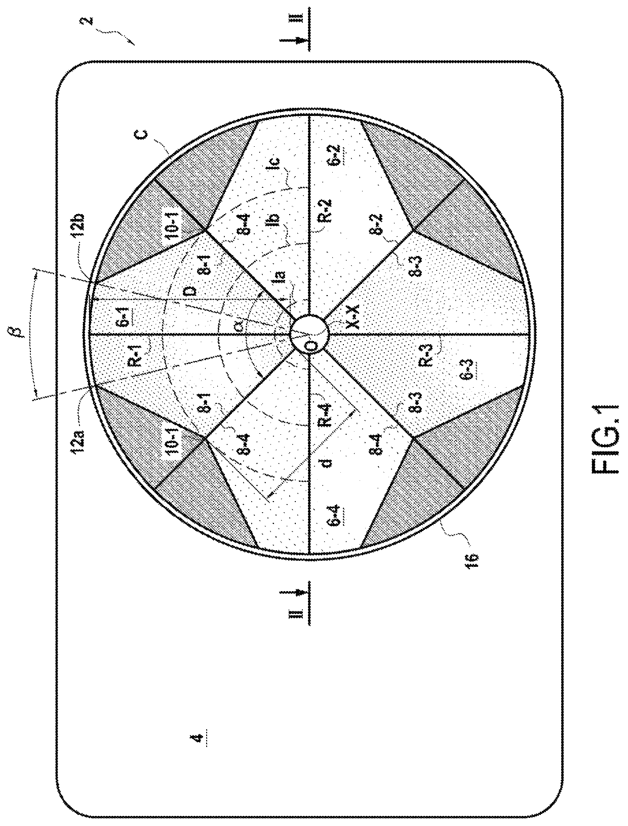
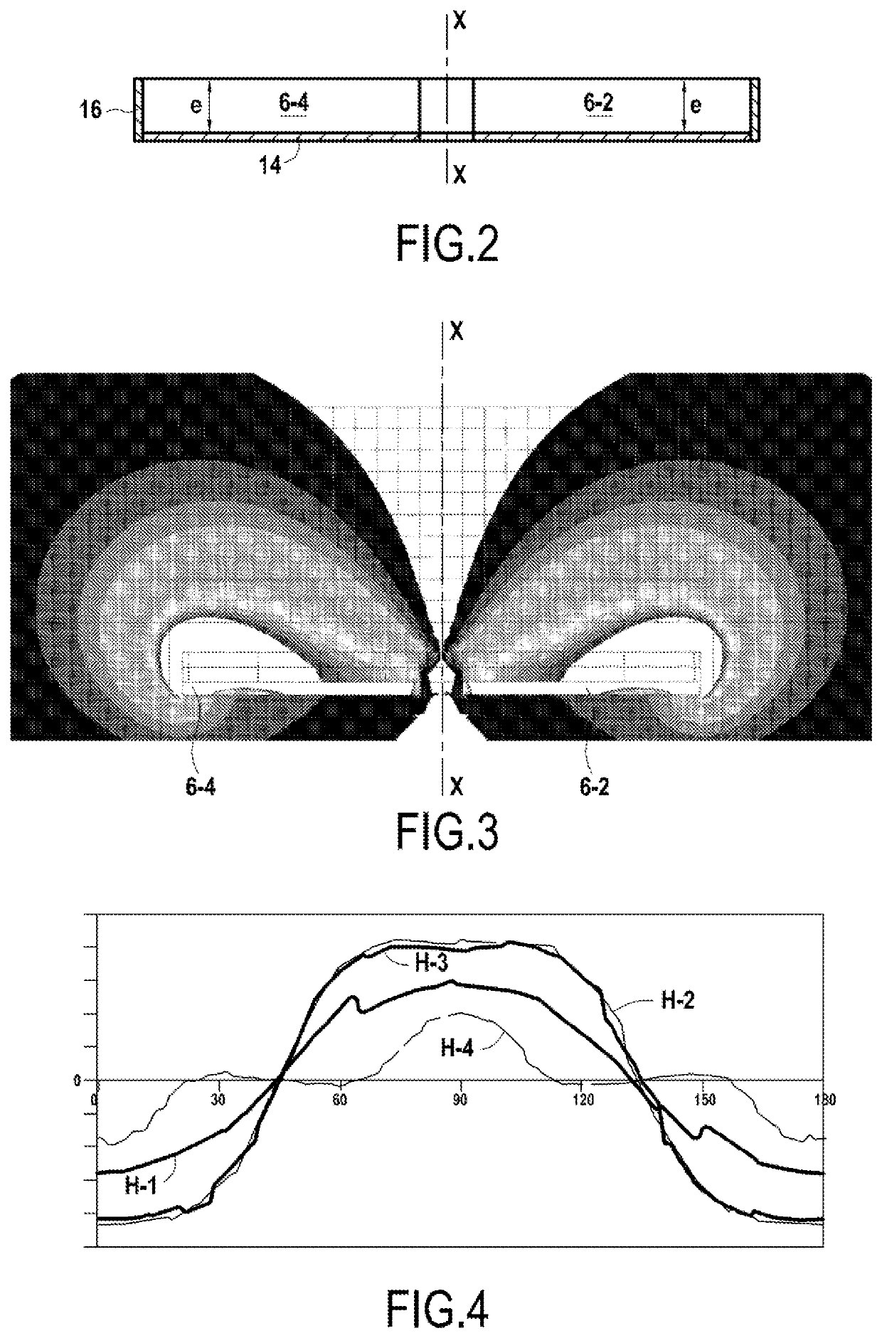
[0027]FIGS. 1 and 2 schematically represent a portable apparatus 2 according to the invention for generating an induced low-frequency sinusoidal electric current intended to be applied to an area of the human body.

[0028]This apparatus 2 comprises a casing 4 inside which are assembled four angular magnet sectors 6-1 to 6-4 having one and the same geometrical shape and centered on one and the same axis of rotation X-X. These four angular magnet sectors 6-1 to 6-4 are contained inside a circle C of diameter D and of center O.

[0029]More precisely, the angular magnet sectors 6-1 to 6-4 are angularly spaced apart from one another about the axis of rotation X-X and are disposed such that the polarity (North or South) of two adjacent angular magnet sectors is opposite. In other words, two angular magnet sectors which are diametrically opposed have the same polarity.

[0030]Thus, on the example represented in FIGS. 1 and 2, the angular magnet sectors 6-1 and 6-3 have a polarity N, whereas the ...


PUM


Abstract

A portable apparatus for generating an induced low-frequency sinusoidal electric current in an area of the human body includes four angular magnet sectors inscribed within the same circle, centered on the same axis of rotation, and spaced angularly apart from one another. The polarity of two adjacent angular magnet sectors is opposed, and a motor for rotating at a predetermined speed the angular magnet sectors is about the axis of rotation to generate an induced sinusoidal current at a predefined frequency. Each angular magnet sector includes the same geometrical shape with an internal angular opening of 90°, an external angular opening between 20° and 50°, and two lateral edges defining a radius extending over a distance, which is between one-third and two-thirds of a distance separating the axis of rotation from the free end of the magnet sectors.

Description

BACKGROUND OF THE INVENTION[0001]The present invention relates to the general field of magnetic therapy, and particularly to portable apparatuses which generate an induced low-frequency sinusoidal electric current intended to be applied to an area of the human body with the aim of exerting an analgesic and anti-inflammatory action.[0002]In a known manner, to generate an induced electric current, magnetic therapy uses a variable magnetic field, particularly to relieve articular and periarticular pain, this variable magnetic field being created by a magnetic source, a coil or a magnet. In the case of magnets, these latter are set in motion to create the induced current.[0003]Magnetic therapy is generally implemented using an apparatus (usually portable) displaced at the level of the area of the body to be treated, this apparatus enclosing magnets, for example rotary magnets, and a motor to allow these magnets to generate a variable magnetic field inducing an electric field proportiona...

Claims


Application Information

Patent Timeline
Patent Type & Authority Patents(United States)
IPC IPC(8): A61N1/40A61N2/12
CPCA61N1/40A61N2/12A61N2/06A61N2/008
Inventor CREPIN, GÉRARDMENEROUD, PATRICKRUDENT, PASCAL
Owner G C TECH
Why Eureka
Try Eureka