Flat antenna for satellite communication

a satellite communication and antenna technology, applied in the direction of antenna arrays, electrical devices, antenna adaptation in movable bodies, etc., can solve the problems of limiting the number of directions in which the antenna can be pointed, unable to operate in two very different frequency bands at the same time, and unable to achieve simultaneous operation in two very different frequency bands. , to achieve the effect of limiting the radiation of the array of monopoles

Active Publication Date: 2018-07-31
INEO DEFENSE
View PDF4 Cites 0 Cited by
  • Summary
  • Abstract
  • Description
  • Claims
  • Application Information

AI Technical Summary

Benefits of technology

[0016]Thus, the invention makes it possible to continuously scan all directions associated with each position of the movable horn. The invention makes it possible to fix the antenna on a plane surface, thus limiting the fragility of the antenna and improving the aerodynamic shape of the carrier of the antenna.
[0019]According to one embodiment, said adaptation means also comprises an array of sensor monopoles fixed on at least one metallic plate, the at least one coaxial cable being connected between said array of sensor monopoles and the at least one radiating line. The sensor monopoles are connected as an array and are able to tap off the energy emitted by the horn at a spacing of less than ½ of a wavelength. The array of sensor monopoles may consist of metallic single strands (monopoles) or of slots or of any other type of elementary antenna. This embodiment thus makes it possible to transmit the energy captured by the horn to the radiating lines.
[0020]According to one embodiment, said array of sensor monopoles comprises a surface closed by a metallic reflector. The metallic reflector makes it possible to limit the radiation of the array of monopoles on the horn side.
[0022]According to one embodiment, the length of the at least one coaxial cable is adapted to introduce an additional delay making it possible to obtain an initial fixed pointing in such a way that the total pointing varies from 0° to 60° for a symmetric displacement of the horn of about ±30°. This embodiment, associated with the 360° global rotation of the antenna about its axis z, makes it possible to contain all the directions in a cone of half-angle 60° centered on the direction normal to the antenna.
[0024]According to one embodiment, said radiating board comprises several radiating lines spaced apart by about half a wavelength. This embodiment makes it possible in particular to avoid problems related to array lobes.

Problems solved by technology

However, the direction of the pointing in terms of a varies with the wavelength λ and does not allow simultaneous operation in two very different frequency bands such as in the Satcom Ka band for example (20 GHz when receiving, 30 GHz when sending).
However, this solution limits the number of directions in which the antenna can be pointed as a function of the number of sources.
Moreover, the installation of a linear array of sources and means of electronic selection increases the bulkiness of the flat antenna.

Method used


Image

  • Flat antenna for satellite communication
  • Flat antenna for satellite communication
  • Flat antenna for satellite communication

Examples


Embodiment Construction

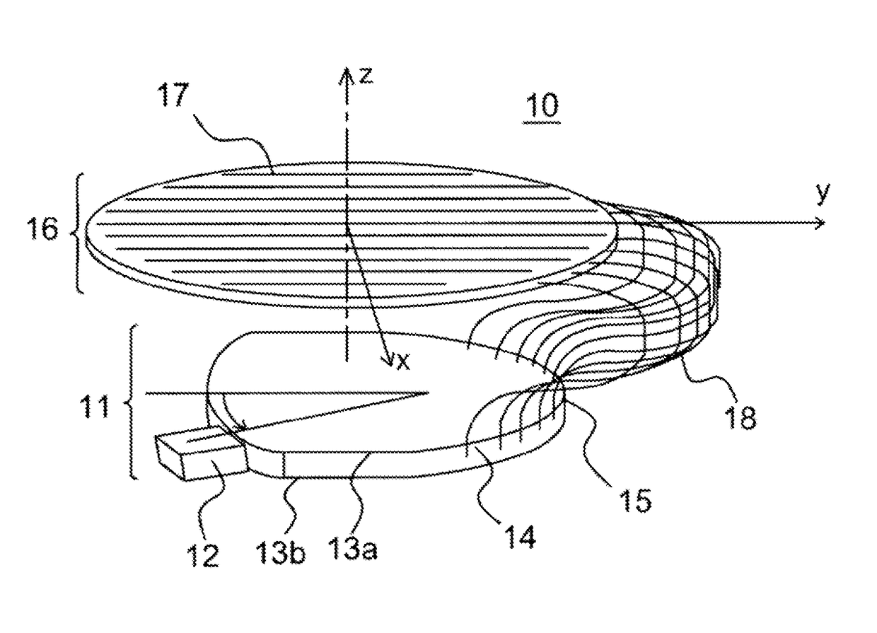
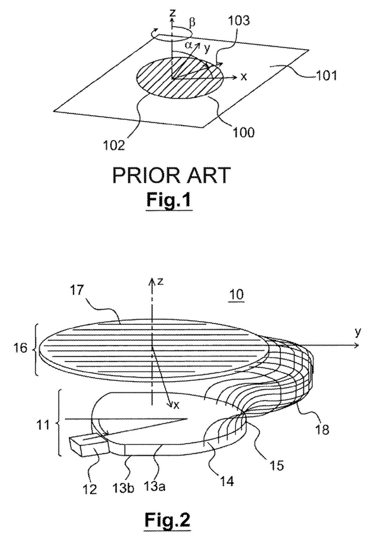
[0031]FIG. 2 reveals a flat satellite telecommunications antenna 10 consisting of a radiating board 16 linked to an adaptation means 11 able to modify the delays of the fields emitted or received by the radiating board 16.

[0032]The radiating board 16 extends in a plane xy and comprises several radiating lines 17 disposed along the axis y at a spacing of about half a wavelength along the axis x. Each radiating line 17 consists of an alignment of N radiating elements (not represented), for example dipoles, patches or slots disposed at a spacing of less than a wavelength along the y axis and fed by a distributor comprising one input and N outputs.

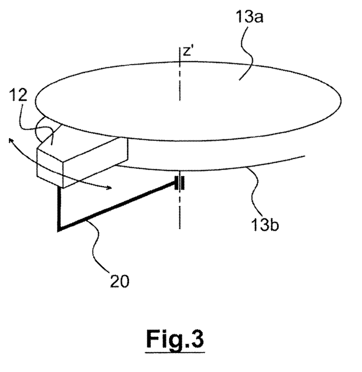
[0033]The adaptation means 11 consists of a horn 12 movable in rotation between two metallic plates 13a and 13b parallel to the radiating board 16. The horn 12, represented in FIG. 3, is movable in rotation about the axis z′ (parallel to or coincident with the axis z) extending in a direction normal to the plane xy. The mobility of the horn 12...


PUM


Abstract

A flat antenna for satellite communication includes a radiating board. The radiating board includes at least one radiating line, and an adapter configured to modify the delay of the fields transmitted or received by the radiating line. The adapter includes a horn mobile in rotation between the two metal plates containing a sensor array. The horn is also mobile in rotation between at least one coaxial cable connected between at least one sensor of the network and the radiating line. The length of the coaxial cable is suitable for introducing a delay required to focus the wave radiated by the radiating line.

Description

RELATED APPLICATIONS[0001]This application is a § 371 application from PCT / EP2015 / 062681 filed Jun. 8, 2015, which claims priority from French Patent Application No. 14 55391 filed Jun. 13, 2014, each of which is incorporated herein by reference in its entirety.FIELD OF THE INVENTION[0002]The present invention pertains to the field of flat antennas for satellite telecommunications. The invention is particularly adapted for aircraft.[0003]The invention finds a particularly advantageous application for sending and receiving data to or from a satellite in particular for satellite telecommunications of Satcom type (acronym of “Satellite communication”).BACKGROUND OF THE INVENTION[0004]For certain telecommunications applications, in particular airborne applications, it is necessary to use flat antennas of very small thickness so as not to modify the aerodynamic profile of the carrier, for example when the antenna is positioned on the surface of an aircraft.[0005]These telecommunication a...

Claims


Application Information

Patent Timeline
Patent Type & Authority Patents(United States)
IPC IPC(8): H01Q9/04H01Q1/28H01Q15/14
CPCH01Q9/0407H01Q15/14H01Q1/288H01Q1/286H01Q3/04H01Q3/32H01Q21/061
Inventor COLLIGNON, GERARD
Owner INEO DEFENSE
Why Eureka
Try Eureka