
Measurement while drilling bi-directional pulser operating in a near laminar annular flow channel

a technology of laminar annular flow and measurement while drilling, which is applied in the direction of survey, instrument, borehole/well accessories, etc., can solve the problem of high energy consumption

Active Publication Date: 2007-02-20
TELEDRILL
View PDF36 Cites 71 Cited by
  • Summary
  • Abstract
  • Description
  • Claims
  • Application Information

AI Technical Summary

Benefits of technology

The solution enables cleaner, reproducible pressure pulses with reduced energy consumption, eliminating the need for continuous field engineers and downtime, and allows for increased data bit rates and formation resolution without losing signal quality.

Problems solved by technology

Current devices also require onsite adjustment of the pulser according to the flow volume and fluid pressure and require higher energy consumption due to resistance of the fluid flow as it flows downward in the drill collar.

Method used


Image

  • Measurement while drilling bi-directional pulser operating in a near laminar annular flow channel
  • Measurement while drilling bi-directional pulser operating in a near laminar annular flow channel
  • Measurement while drilling bi-directional pulser operating in a near laminar annular flow channel

Examples


Embodiment Construction

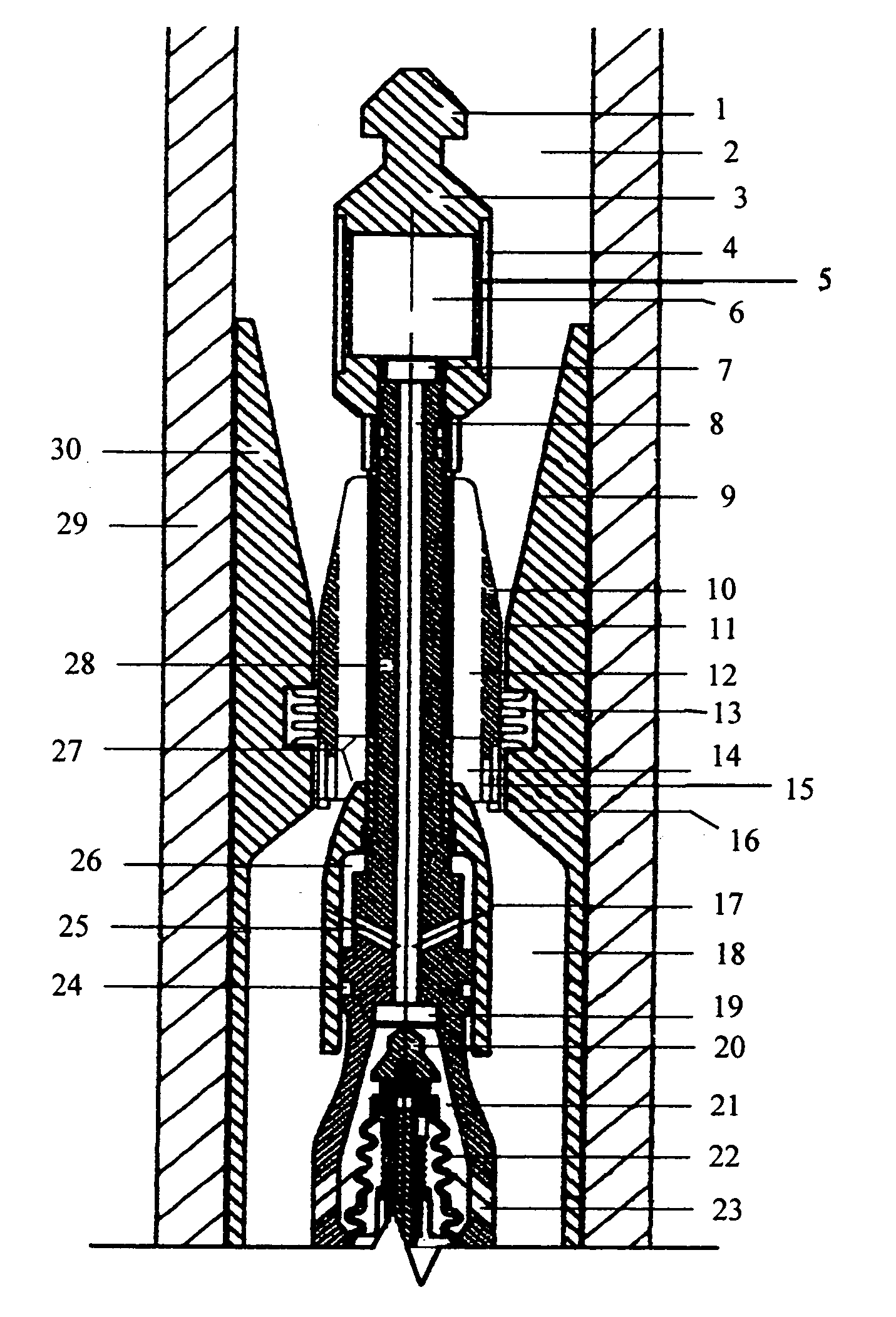
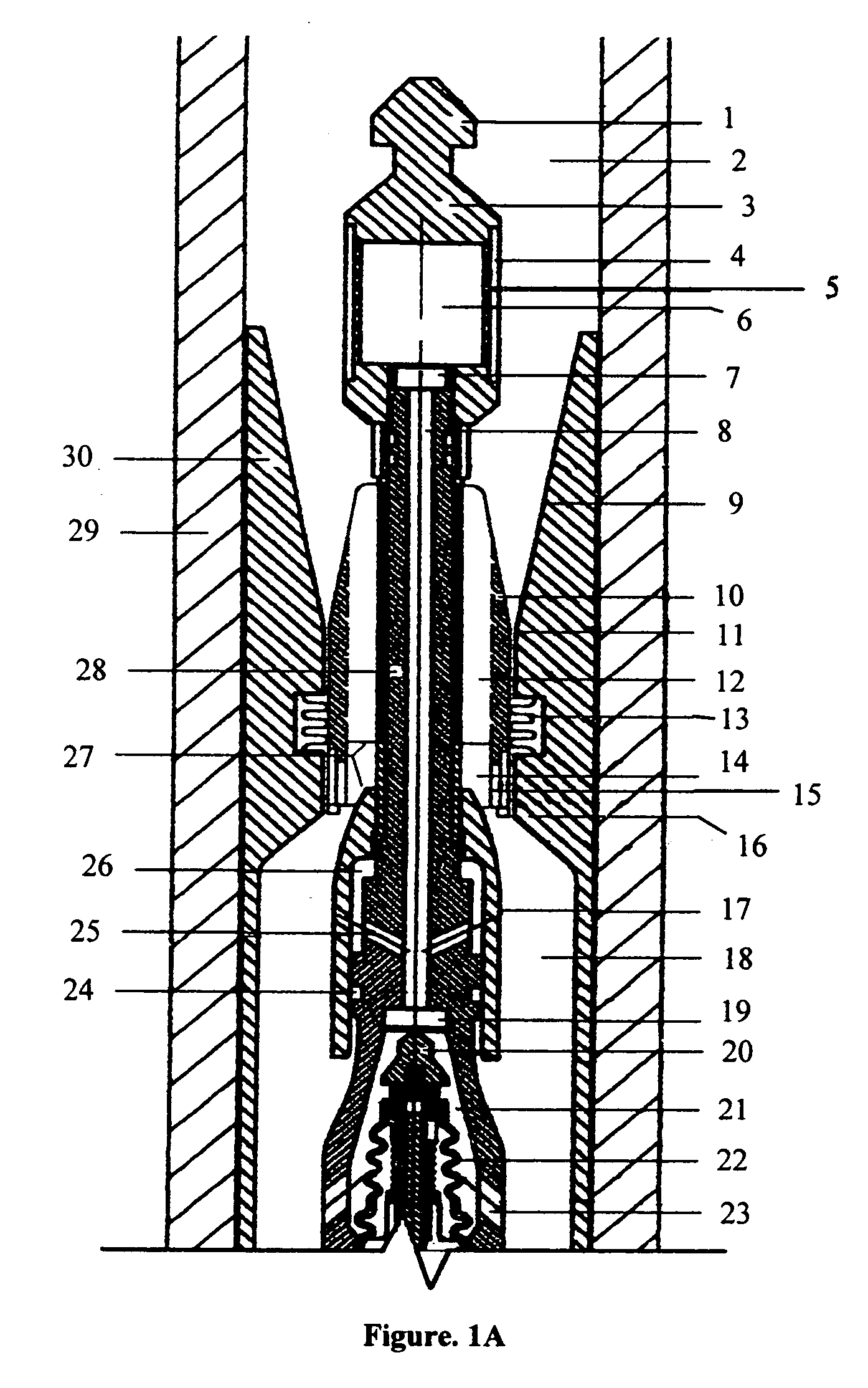
[0038]The present invention will now be described in greater detail and with reference to the accompanying drawing. With reference now to FIG. 1, the device illustrated produces pressure pulses in drilling fluid flowing through a tubular drill collar [29] and upper annular drill collar flow channel [2]. The flow guide [30] is secured to the inner diameter of the drill collar [29]. The centralizer [36] secures the lower portion of the pulse generating device and is comprised of a non-magnetic, rigid, wear resistant material with outer flow channels.

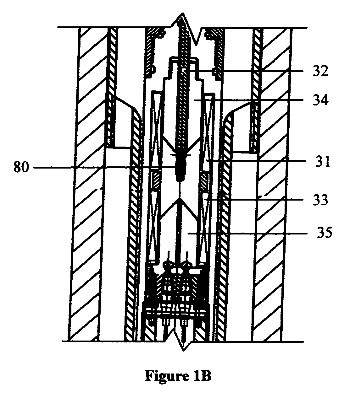
[0039]In the first (unsealed) position the poppet assembly [20] is not engaged within the poppet seat [19]. Energizing a bottom solenoid [33] pulls the actuator assembly [80] until it is flush with the bottom flux concentrator [35]. The solenoid actuator shaft [32], which is rigidly attached to the actuator assembly [80], moves to pull the poppet assembly [20] away from the poppet seat [19]. In the unsealed position, fluid flows past the f...


PUM


Abstract

A device, method, and system for creating a pressure pulse from drilling fluid within a drill string in a down hole drill collar for enabling measurement-while drilling. The device and system are designed such that primarily laminar flow exists in the area surrounding the pulser apparatus. The method associated with the reproducible and essentially noise-free pulses occurs when a pulser bell is manipulated in an upward and downward direction by a combination of the solenoid activation of a bi-directional poppet to redirect the fluid flow from the pressure reservoir to and from a sliding pressure chamber and associated upper and lower flow connecting channels. The pulse or non-pulse is converted into a digital signal uphole by a pressure transducer in conjunction with a decoding algorithm. It is then displayed to the driller and oilfield operators as useful directional and formation information that help the oilfield operator for uphole decision making regarding directional drilling. Additional pulsers can be added to the tool so that higher data bit rates can be accomplished. These higher data bit rates will provide for more comprehensive data collection thereby reducing drilling costs and optimizing oil field yields. The higher bit rate allows for more sensors that can send additional and improved information uphole without the use of open hole wire line logging which is impossible to accommodate while drilling horizontally.

Description

BACKGROUND OF THE INVENTION[0001]1. Field of Invention[0002]The current invention includes an apparatus and a method for creating a pressure pulse within drilling fluid that is generated by selectively activating solenoids that initiate flow driven bi-directional pulses. Features of the device include operating a pulser bell within a specially designed annular flow channel designed to reduce turbulent flow of the drilling fluid in a measurement-while-drilling device to provide for reproducible pressure pulses that are translated into relatively noise-free signals. The pulse is then received “up hole” as a series of signals that represent pressure variations which may be interpreted as gamma ray counts per second, azimuth, etc. by oilfield engineers and managers to recognize how to increase yield in oilfield operations.[0003]Current purser technology includes pursers that are sensitive to different fluid pump down hole pressures, and flow rates, and require field adjustments to pulse...

Claims


Application Information

Patent Timeline
Patent Type & Authority Patents(United States)
IPC IPC(8): H04H9/00E21B47/24E21B47/01H04H60/31
CPCE21B47/187E21B47/24
Inventor KUSKO, DAVIDMASAK-ROZIER, LEGAL REPRESENTATIVE, ADRIENNE D.MASAK, DECEASED, PETER
Owner TELEDRILL
Learn More