
Static mixing device

a technology of mixing device and mixing chamber, which is applied in the direction of couplings, braking systems, transportation and packaging, etc., can solve the problems of associated energy costs and achieve the effect of facilitating space efficient fitting

Active Publication Date: 2009-04-07
SAINT GOBAIN PERFORMANCE PLASTICS CORP
View PDF9 Cites 10 Cited by
  • Summary
  • Abstract
  • Description
  • Claims
  • Application Information

AI Technical Summary

Benefits of technology

The static mixing device effectively mixes fluids without dynamic elements, is compact, reduces pressure drop, and maintains fluid purity, making it suitable for high-purity and corrosive fluid applications.

Problems solved by technology

While this is one method of forming a mixed output, it is one that can involve a number of moving parts that can fail or otherwise have a limited service life.
Additionally, the use of such dynamic mixing device comprising a moving element requires an energy input, which has associated therewith a certain energy cost.
A further issue associated with the use of such dynamic mixing device relates to its packaging size, which to ensure a good degree of mixing is relative large.

Method used


Image

  • Static mixing device
  • Static mixing device
  • Static mixing device

Examples


Embodiment Construction

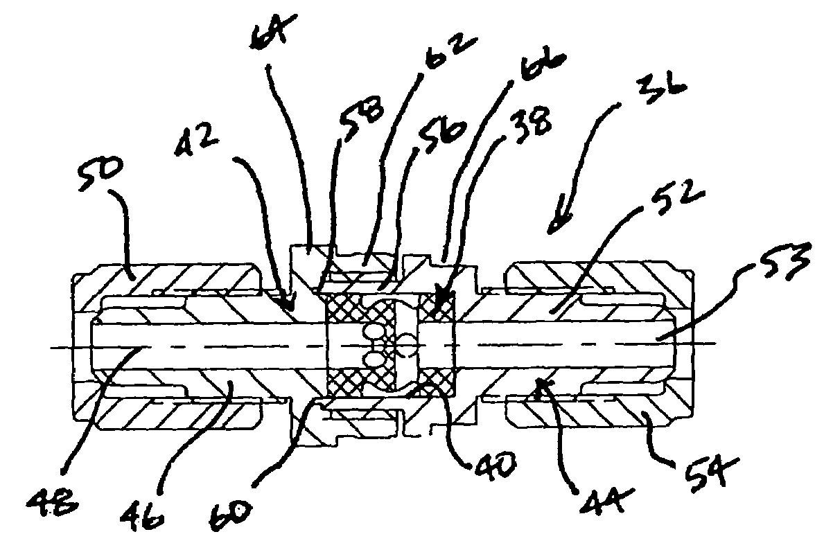
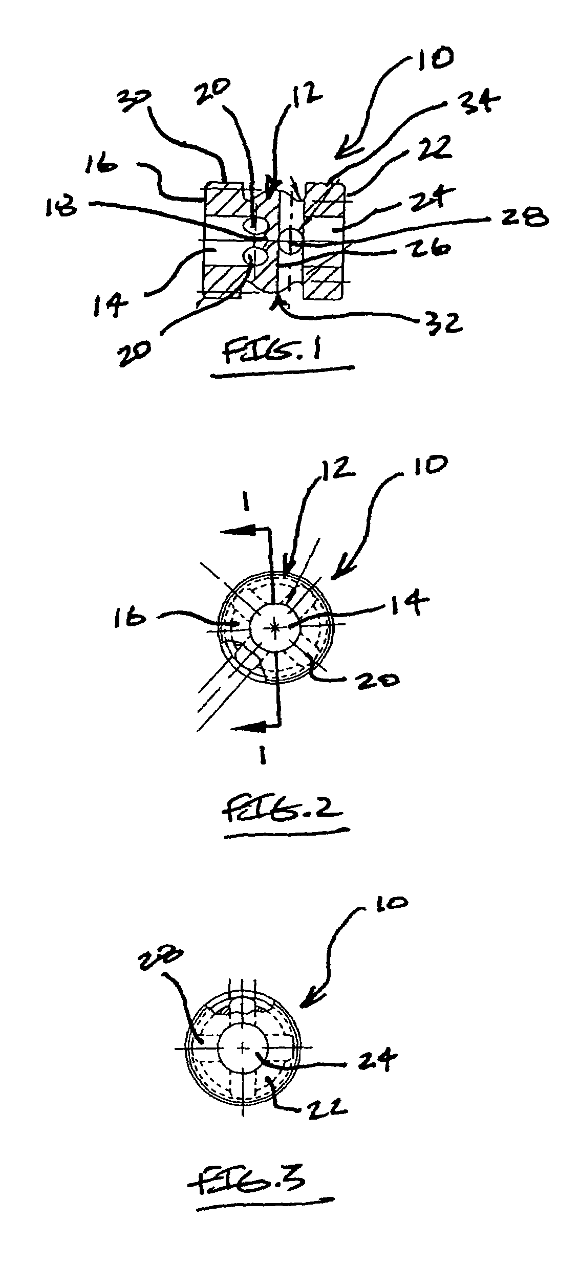
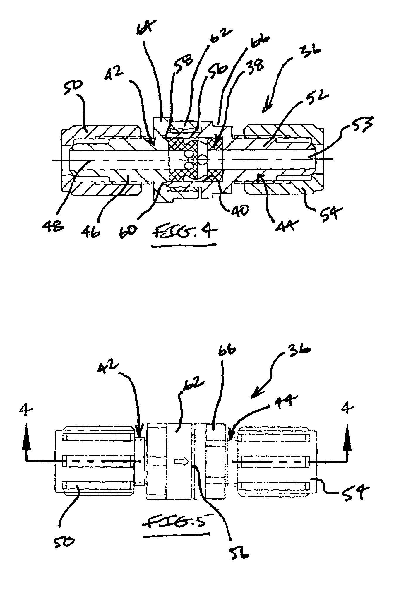
[0019]Mixing devices, constructed according to principles of this invention, are configured to provide a mixed output stream of fluids or gases in a manner that does not involve the use of a dynamic element, and is packaged in a manner that is space efficient. Further, mixing devices of this invention are constructed having a minimal pressure drop therethrough to reduce any unwanted pressure affect when placed into a process flow system. Further, mixing devices of this invention are constructed to have an internally swept volume with a zero or minimal internal hold up volume, and can be formed from materials that facilitate use with high purity process fluids such as corrosive liquids and the like without introducing unwanted contamination therein. Specifically, mixing devices of this invention can be formed from wetted elements made from chemically inert materials resistant to corrosive, abrasive, and caustic process fluids, are not formed from metal, and are constructed without th...


PUM


Abstract

Mixing devices comprise a mixing element having a body with a fluid inlet port, and a fluid outlet port that is separated from the fluid inlet port. Fluid outlet passages extend through a body wall section defining the fluid inlet port, and fluid inlet passages extend through a body wall section defining the fluid outlet port. The body includes an outside surface having a reduced diameter section, and the fluid inlet and outlet passages are positioned axially along the reduced diameter section. The mixing element is statically disposed within an internal chamber of a housing, and an annular volume is defined between an inside surface of the internal chamber and the mixing element reduced diameter section to facilitate passage and mixing of fluid within the annular volume. The mixing element total inlet area is approximately equal to its total outlet area to minimize unwanted pressure drop.

Description

FIELD OF THE INVENTION[0001]The present invention relates generally to mixing devices used for combing two or more streams of fluid or gas together to provide a single mixed flow output and, more particularly, to a static mixing device that that provides such mixed flow output in a construction that is compact and efficient.BACKGROUND OF THE INVENTION[0002]Many processes are know in the art that require the mixing together of two of more fluid or gas streams to provide a mixed output stream. These processes can be used in any number of applications. A particular application where the mixing together of fluid streams is used is the semiconductor manufacturing industry. For example, during the process of making semiconductors, it is necessary to use a fluid stream that comprises a mixed flow of two or more different independent fluids.[0003]Conventionally, the combining or mixing together of two of more fluid or gas streams is achieved by using a dynamic mixing device, e.g., a device ...

Claims


Application Information

Patent Timeline
Patent Type & Authority Patents(United States)
IPC IPC(8): B01F5/00
CPCB01F5/0644B01F2215/0096Y10T137/87281Y10T137/87265B01F25/4323B01F2101/58
Inventor KINGSFORD, KENJI A.
Owner SAINT GOBAIN PERFORMANCE PLASTICS CORP
Learn More