
Clock signal generation circuits and methods using phase mixing of even and odd phased clock signals

a clock signal and phase mixing technology, applied in the direction of generating/distributing signals, pulse techniques, instruments, etc., can solve problems such as greater jitter

Inactive Publication Date: 2007-02-13
SAMSUNG ELECTRONICS CO LTD
View PDF16 Cites 12 Cited by
  • Summary
  • Abstract
  • Description
  • Claims
  • Application Information

AI Technical Summary

Benefits of technology

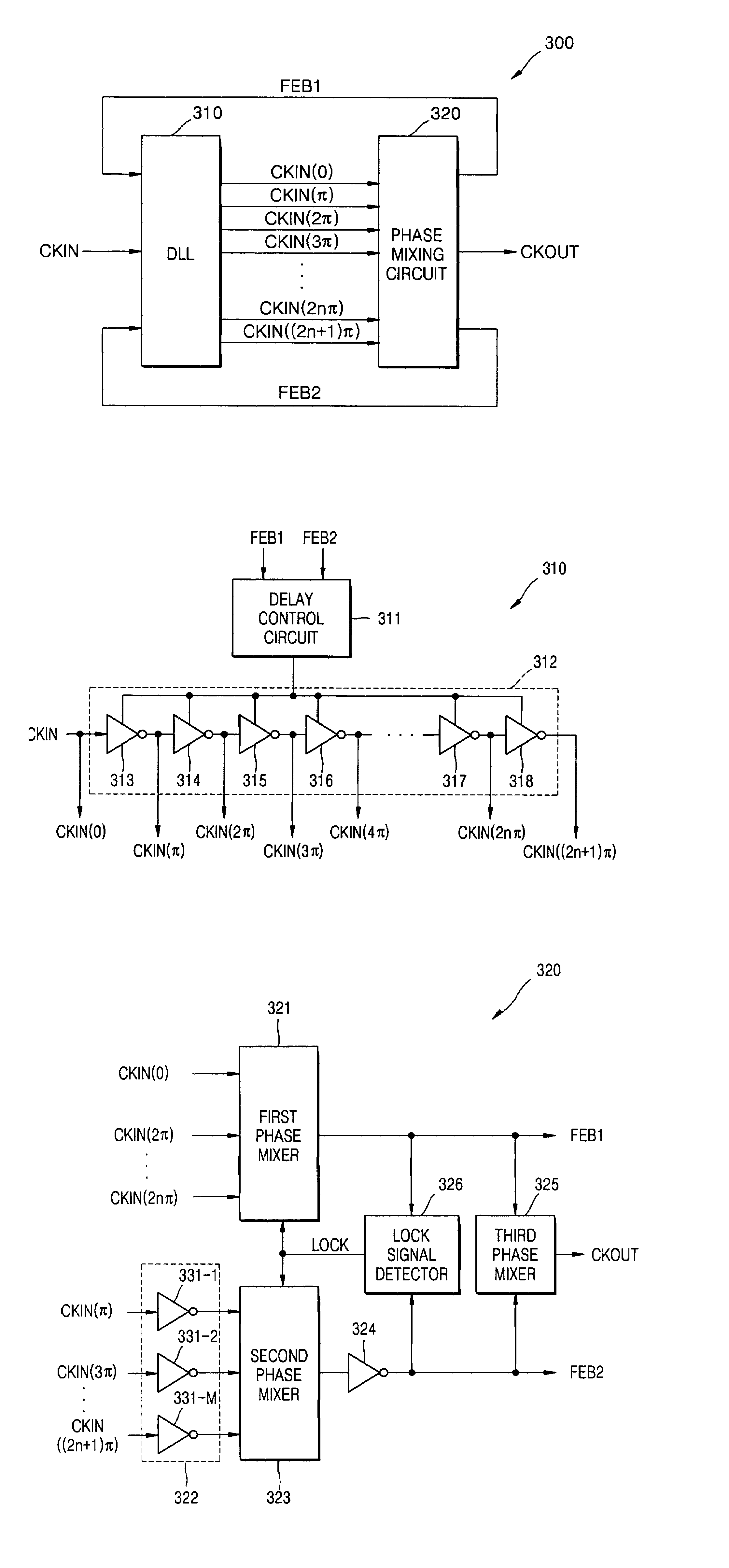
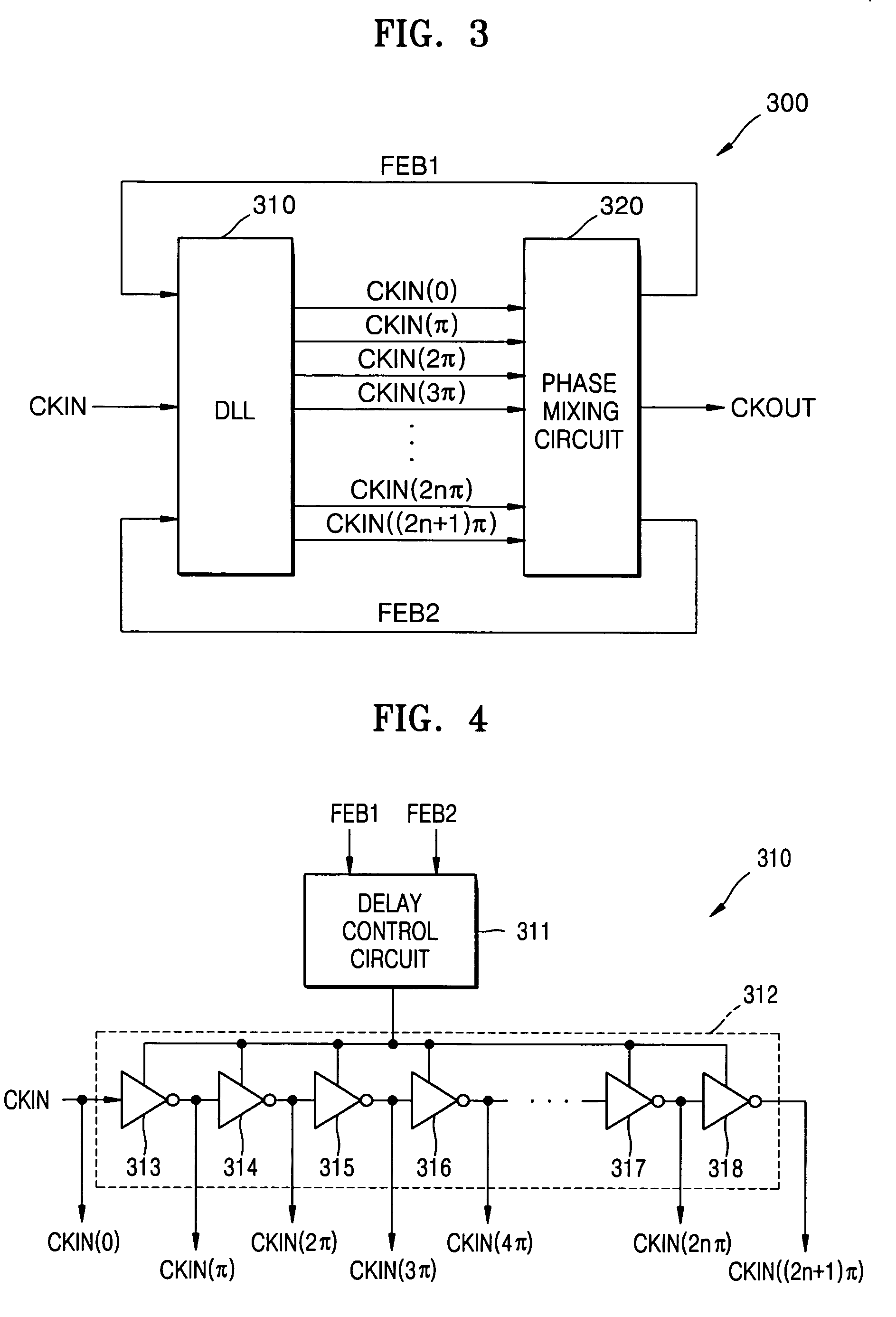
The present invention relates to a clock signal generation circuit that generates multiple phased clock signals with uniform delays. The circuit includes a Delay Locked Loop (DLL) and a phase mixer that receives the input clock signal and the feedback signals from the DLL. The phase mixer then generates the output clock signal by mixing the first and second groups of clock signals. The circuit can also include a lock detector that controls the phase mixers based on the phase difference between the input clock signal and the feedback signals. The technical effect of this invention is to provide a more accurate and reliable clock signal for use in electronic devices.

Problems solved by technology

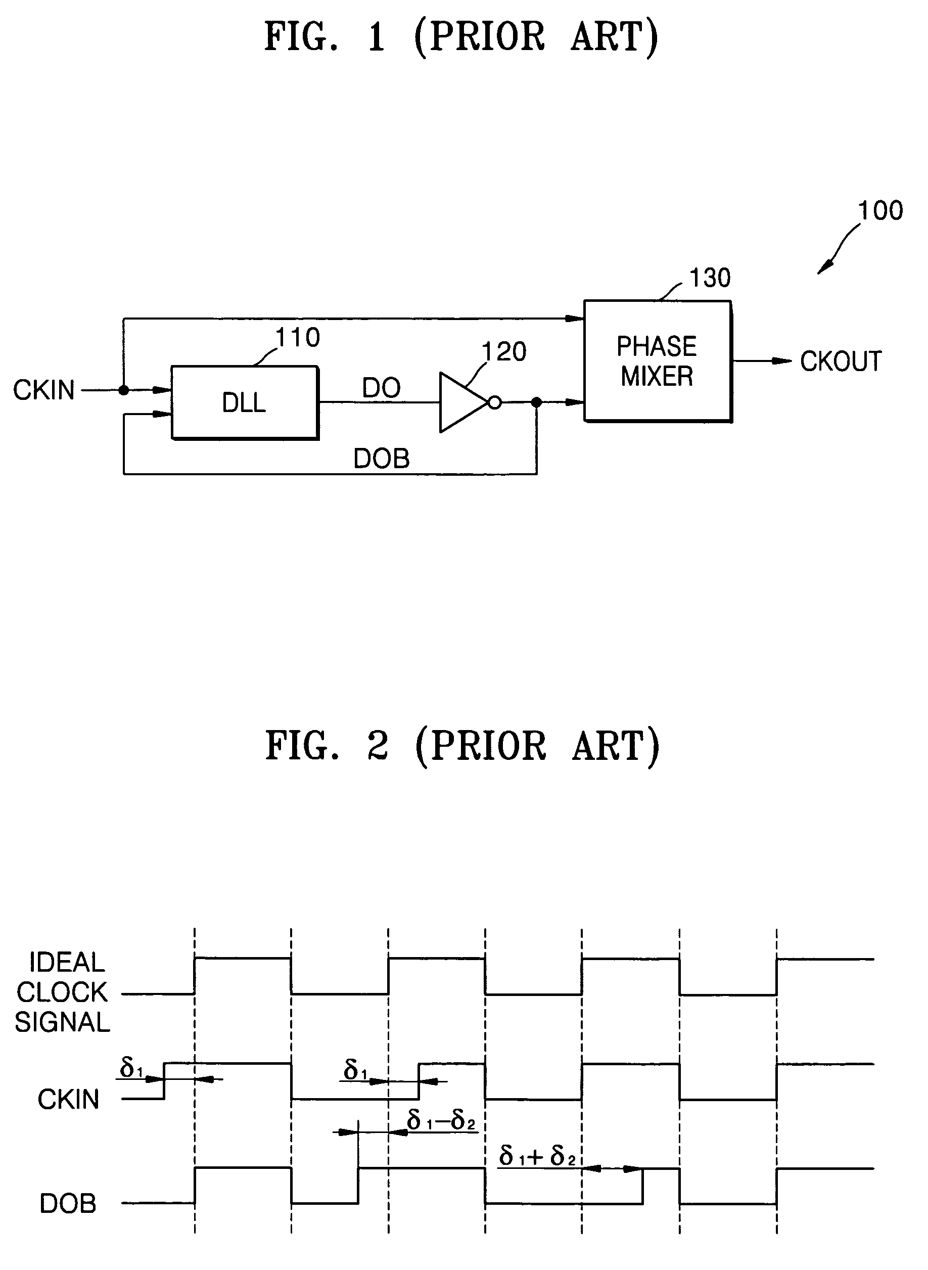
However, using the oscillator-type phase filter can change a frequency of the output clock signal CKOUT and cause jitter accumulation, which can produce a greater jitter.

Method used


Image

  • Clock signal generation circuits and methods using phase mixing of even and odd phased clock signals
  • Clock signal generation circuits and methods using phase mixing of even and odd phased clock signals
  • Clock signal generation circuits and methods using phase mixing of even and odd phased clock signals

Examples


Embodiment Construction

[0019]The present invention will now be described more fully with reference to the accompanying drawings, in which embodiments of the invention are shown. This invention may, however, be embodied in different forms and should not be construed as being limited to the embodiments set forth herein. Rather, these embodiments are provided so that this disclosure will be thorough and complete, and will fully convey the scope of the invention to those skilled in the art. Like numbers refer to like elements. As used herein the term “and / or” includes any and all combinations of one or more of the associated listed items.

[0020]The terminology used herein is for the purpose of describing particular embodiments only and is not intended to be limiting of the invention. As used herein, the singular forms “a”, “an” and “the” are intended to include the plural forms as well, unless the context clearly indicates otherwise. It will be further understood that the terms “comprises” and / or “comprising,”...


PUM


Abstract

A clock signal generation circuit includes a Delay Locked Loop (DLL) that, responsive to an input clock signal and first and second feedback clock signals, generates a plurality of phased clock signals time-shifted with respect to one another. The clock signal generation circuit further includes a phase mixer that receives the plurality of phased clock signals, that phase mixes first and second groups of the plurality of phased clock signals to generate the respective first and second feedback signals, and that phase mixes the first and second feedback signals to generate an output clock signal. The phased plurality of clock signals may be separated by substantially uniform delays, the first group of clock signals may include signals delayed even numbers of delays with respect to the input clock signal, and the second group of clock signals may include signals delayed odd numbers of delays with respect to the input clock signal. Each of the substantially uniform delays may be approximately one-half of a period of the input clock signal.

Description

RELATED APPLICATION[0001]This application claims the priority of Korean Patent Application No. 2004-13009, filed on Feb. 26, 2004, in the Korean Intellectual Property Office, the disclosure of which is incorporated herein in its entirety by reference.BACKGROUND OF THE INVENTION[0002]The present invention relates to clock signal generation circuits and methods, and more particularly, to clock signal generation circuits and methods that provide duty cycle control.[0003]Many systems, including semiconductor memory devices, such as RDRAM (Rambus Dynamic Random Access Memory) and DDR (Double Data Rate) memory devices, systems for processing video signals and / or audio signals, and communication systems, include a clock generation circuit that uses a DLL (Delay Locked Loop) to generate an accurate clock signal. A typical clock signal generation circuit processes an input clock signal and generates a new clock signal with a predetermined duty factor. The duty factor is a percentage of a val...

Claims


Application Information

Patent Timeline
Patent Type & Authority Patents(United States)
IPC IPC(8): H03L7/00H03K5/13H03L7/06H03L7/081
CPCH03L7/0812H03K5/13
Inventor PARK, KWANG-IL
Owner SAMSUNG ELECTRONICS CO LTD
Learn More