Cutter body, rotary tool, and method for assembling the rotary tool

a rotary tool and cutter body technology, applied in the direction of manufacturing tools, screwdrivers, threaded fasteners, etc., can solve the problems of high probability of shortened cutting insert life, concentration of load on a particular cutting insert, and etc., to prevent accidental change of cutting edge height of cutting inserts, good balance between fluidity and viscosity, good balance

Inactive Publication Date: 2007-01-16
NGK SPARK PLUG CO LTD
View PDF19 Cites 24 Cited by
  • Summary
  • Abstract
  • Description
  • Claims
  • Application Information

AI Technical Summary

Benefits of technology

[0022]In the cutter body of (1) above, the wrench reception socket of the fastened second screw and / or that of the adjustment-completed adjustment screw is sealed. Thus, for example, when the cutting insert is to be replaced, a wrench is not inserted into the wrench reception socket of the adjustment screw or into that of the second screw. Therefore, the adjustment screw or the second screw is not rotated by mistake, thereby preventing an accidental change in the cutting edge height of the cutting insert.
[0023]In the case where, as described in (2) above, the wrench reception socket is filled with resin, such as silicone rubber, so as to be sealed, when readjustment becomes necessary, unsealing can be readily performed. Thus, adjustment and sealing can be repeated any number of times. No particular limitation is imposed on the sealing resin. However, silicone rubber is preferred, because of good balance between fluidity and viscosity and good balance between adhesiveness and removability.
[0024]In the case where, as described in (3) above, the wrench reception socket is roughened on at least an inner wall surface, since the resin is caught in the roughened surface, an anchor effect is produced, thereby preventing the resin from coming off of the wrench reception socket, which could otherwise result from high-speed rotation.
[0025]The cutter body of (4) above can also prevent the resin from coming off of the wrench reception socket, which could otherwise result from high-speed rotation.
[0026]In the case where, as described in (5) above, the wrench reception socket is deformed so as to be sealed, additional material cost is not incurred.
[0027]Specifying the shape of the wrench reception socket as described in (6) above can also yield an effect similar to that of sealing the wrench reception socket.

Problems solved by technology

When a tool is applied to cutting while the cutting inserts differ in cutting edge height, satisfactory surface roughness may fail to be obtained, or the life of the tool may be shortened.
Particularly, in the case of cutting inserts each having a diamond cutting edge, an irregular cutting edge height causes concentration of load on a particular cutting insert.
As a result, the life of that cutting insert is highly likely to be shortened because of low toughness.
In many cases, a rotary tool for cutting an aluminum workpiece is rotated at high speed and is thus highly susceptible to an irregular cutting edge height among cutting inserts.

Method used


Image

  • Cutter body, rotary tool, and method for assembling the rotary tool
  • Cutter body, rotary tool, and method for assembling the rotary tool
  • Cutter body, rotary tool, and method for assembling the rotary tool

Examples


Embodiment Construction

[0055]A cutter body, a rotary tool, and an assembly method according to an embodiment of the present invention will next be described with reference to the drawings. However, the present invention should not be construed as being limited thereto. Herein, a milling cutter will be described as an example of the rotary tool of the present invention.

[0056]a) First, a milling cutter will be described.

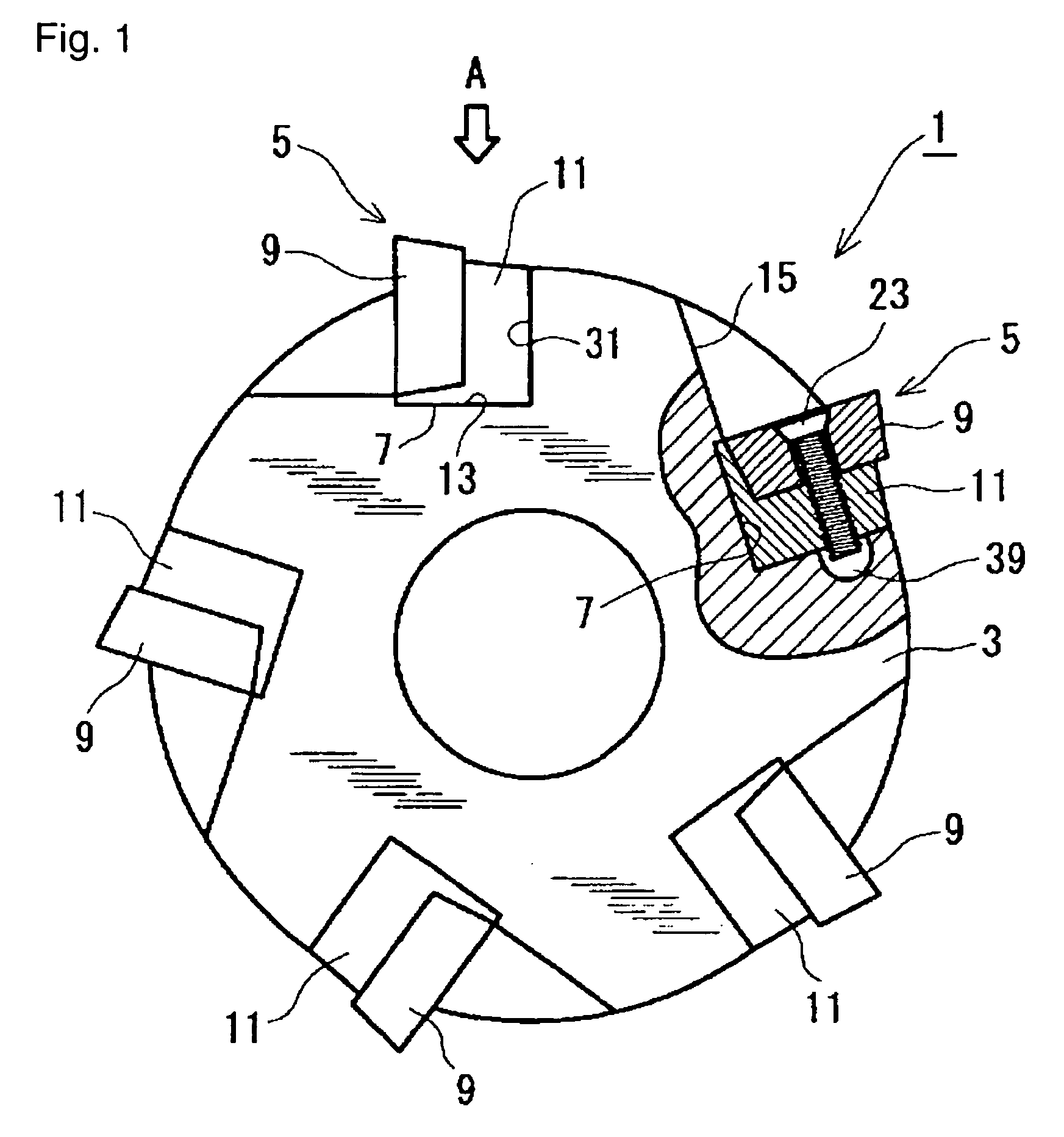
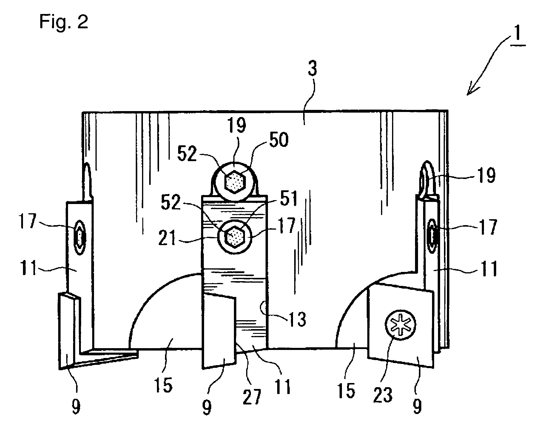
[0057]As shown in FIGS. 1 and 2, a milling cutter 1 of the present embodiment includes a substantially cylindrical cutter body member 3 made of an alloy steel (SCM435, per JIS G4105, 1979). Five cutting sections 5 are provided circumferentially on a distal end portion (a portion located toward the near side in FIG. 1) of the cutter body member 3.

[0058]Specifically, five attachment recesses 7 (see FIG. 4) are provided circumferentially on a distal end portion of the cutter body member 3. Members, such as a cutting insert (hereinafter referred to as an “insert”) 9 made of carbide and a cartrid...


PUM


Abstract

A cutter body which includes cartridges 11 for allowing corresponding cutting inserts 9 to be removably fixed thereto, a cutter body member 3, second screws (cartridge fixation screws 17) for fixing the corresponding cartridges 11 to the cutter body member 3, and adjustment screws 19 for adjusting the positions of the corresponding cartridges 11. A wrench reception socket 51 of each of the fastened second screws 17 and / or a wrench reception socket 50 of each of the adjustment-completed adjustment screws 19 is sealed. A rotary tool (milling cutter 1) is configured such that the cutting inserts 9 are fixed to the corresponding cartridges 11 of the cutter body.

Description

BACKGROUND OF THE INVENTION [0001]1. Field of the Invention[0002]The present invention relates to a cutter body and a rotary tool for use in milling, as well as a method for assembling the rotary tool.[0003]2. Description of the Related Art[0004]Cutters and end mills having a plurality of cutting edges are conventionally known. In these tools, when cutting inserts are mounted, the cutting edge height may vary among the mounted cutting inserts. This is because the cutting edge height varies depending on the fabrication accuracy of cutters and cutting inserts. When a tool is applied to cutting while the cutting inserts differ in cutting edge height, satisfactory surface roughness may fail to be obtained, or the life of the tool may be shortened. Particularly, in the case of cutting inserts each having a diamond cutting edge, an irregular cutting edge height causes concentration of load on a particular cutting insert. As a result, the life of that cutting insert is highly likely to be ...

Claims


Application Information

Patent Timeline
Patent Type & Authority Patents(United States)
IPC IPC(8): B23C5/22B23C5/00B23C5/24F16B39/00
CPCB23C5/00B23C5/2462B23B2260/126Y10T407/1928Y10T407/1932Y10T407/1912B23C2260/72
Inventor TOYOSE, HIDENORI
Owner NGK SPARK PLUG CO LTD
Why Eureka
Try Eureka