Droplet ejecting apparatus

a technology of ejecting apparatus and droplet, which is applied in the direction of piezoelectric/electrostrictive/magnetostrictive devices, coatings, printing, etc., can solve the problems of increasing the cost of manufacturing of stacked piezoelectric bodies or elements, and not achieving a sufficiently high deformation efficiency at an appropriate drive voltage. , to achieve the effect of convenient connection

Active Publication Date: 2007-01-02
BROTHER KOGYO KK
View PDF8 Cites 5 Cited by
  • Summary
  • Abstract
  • Description
  • Claims
  • Application Information

AI Technical Summary

Benefits of technology

[0007]It is therefore an object of the present invention to provide a droplet ejecting apparatus which is free from at least one of the above-identified problems. It is another object of the present invention to provide such a droplet ejecting apparatus which employs a piezoelectric body that can be produced at low cost, be easily polarized, and enjoy improved deformation efficiency at a certain drive voltage. These objects may be achieved according to any one of the following modes of the present invention.
[0008](1) An apparatus for ejecting, from a nozzle communicating with a pressure chamber in which a liquid is accommodated, a droplet of the liquid by deforming a portion of a piezoelectric body and thereby changing a volume of the pressure chamber, the apparatus comprising the piezoelectric body; at least one first internal electrode which is provided in the piezoelectric body, at a first position where the first internal electrode is opposed to the pressure chamber in a first direction; at least one second internal electrode which is provided in the piezoelectric body, at a second position distant from the first position in a second direction perpendicular to the first direction; and a first polarizing electrode and a second polarizing electrode which cooperate with each other to sandwich, in the first direction, at least a first portion of the piezoelectric body that is located between the first and second internal electrodes in the second direction, the first portion of the piezoelectric body being polarized in the first direction by applying a polarizing voltage to the first and second polarizing electrodes, one of the first and second polarizing electrodes being electrically connected to one of the first and second internal electrodes, wherein when a driving voltage is applied to the first and second internal electrodes, a first electric field is produced in the first portion of the piezoelectric body, substantially in the second direction, and a second electric field is produced in a second portion of the piezoelectric body that is located between the one of the first and second polarizing electrodes and an other of the first and second internal electrodes, substantially in the first direction. When the second electric field is produced in the second portion of the piezoelectric body, the second portion is elongated in a direction substantially parallel to the direction in which the second electric field is produced, and is shrunk in a direction perpendicular to the direction of elongation, and this deformation of the second portion promotes or amplifies the deformation of the first portion of the piezoelectric body caused by the first electric field, i.e., the so-called shear deformation of the first portion.
[0009]In this droplet ejecting apparatus, when the driving voltage is applied to the first and second internal electrodes, the first electric field is produced in the first portion of the piezoelectric body located between the first and second internal electrodes, substantially in the second direction perpendicular to the first direction in which the first portion of the piezoelectric body is polarized, so that the first portion of the piezoelectric body is deformed in the shear mode, and additionally the second electric field is produced in the second portion of the piezoelectric body located between the one of the first and second polarizing electrodes and the other of the first and second internal electrodes, so that the second portion of the piezoelectric body is so deformed as to facilitate the deformation of the first portion of the same. Thus, in the droplet ejecting apparatus, the piezoelectric body can enjoy improved deformation efficiency at a given drive voltage. In addition, since the polarizing electrodes are not removed from the piezoelectric body, but are utilized to improve the deformation efficiency of the same, in contrast to a conventional apparatus in which polarizing electrodes are removed from a piezoelectric body, the piezoelectric body of the present apparatus can be manufactured with ease and at low cost.
[0011]According to this mode, the plurality of first internal electrodes and the plurality of second internal electrodes can be easily provided in the piezoelectric body, which contributes to improving the deformation efficiency of the same.
[0013]According to this mode, the two polarizing electrodes can be easily connected to each of a polarizing power source and a driving power source.

Problems solved by technology

However, in the above-described manufacturing method, the removing step in which the polarizing external electrodes are removed by, e.g., etching from the stacked piezoelectric body, is very cumbersome and time-consuming.
This leads to increasing the cost of manufacturing of the stacked piezoelectric body or element.
In addition, since the sheet-stacked piezoelectric element is deformed by just producing the electric field in the direction perpendicular to the direction of polarization of the element, the element cannot enjoy a sufficiently high deformation efficiency at an appropriate drive voltage.

Method used


Image

  • Droplet ejecting apparatus
  • Droplet ejecting apparatus
  • Droplet ejecting apparatus

Examples


second embodiment

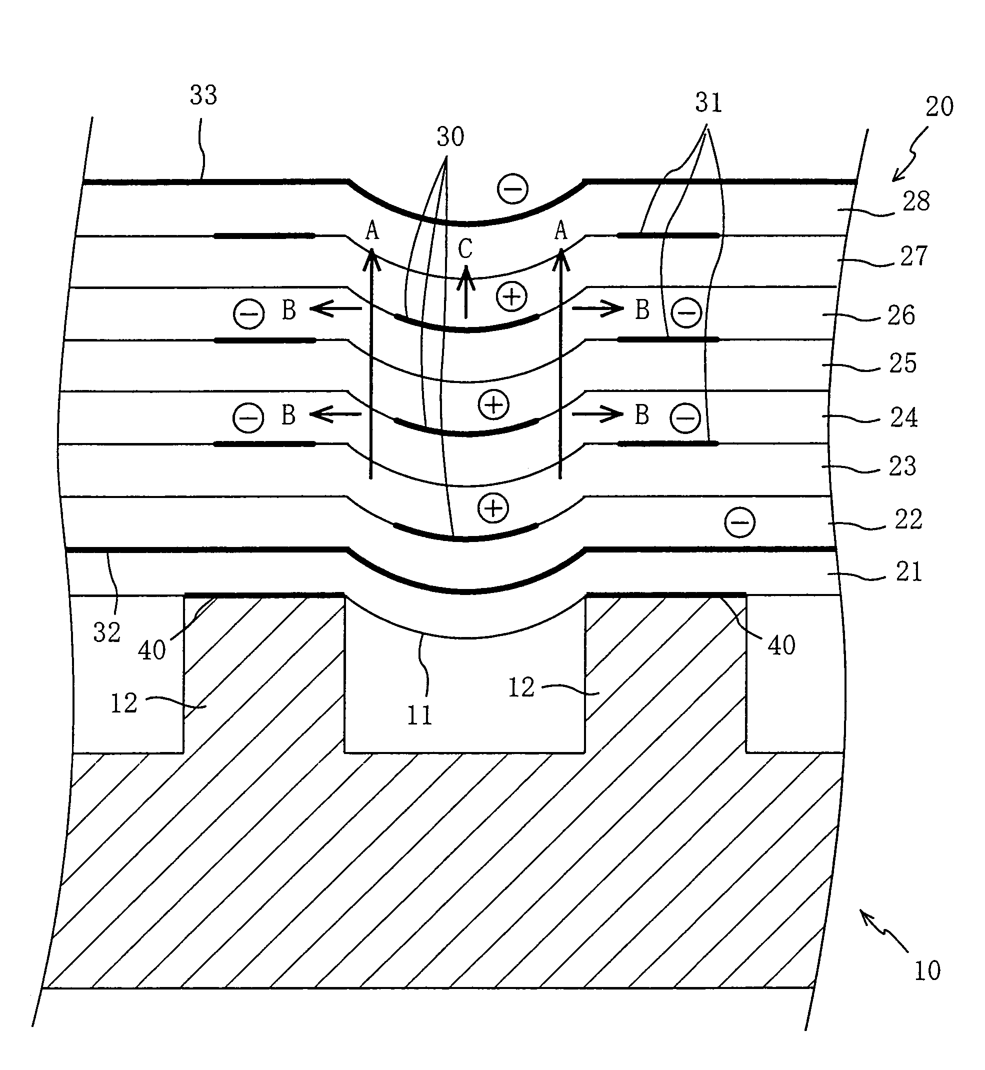
[0048]In the second embodiment, preferably, respective portions of the first polarizing electrode 132 that are aligned with areas, E, in which the second internal electrodes 31 are provided, are removed, in advance, so as not to adversely restrict the elongation and shrinkage of the second and third piezoelectric sheets 22, 23.

[0049]FIG. 8 shows a third embodiment of the present invention that also relates to an ink jet recording head that, however, employs a stacked-type piezoelectric body 220 in place of the stacked-type piezoelectric body 20 or 120 employed in the first or second embodiments. The stacked-type piezoelectric body 220 includes first internal electrodes 230 that are connected to the ground terminal of the drive power source 41, and second internal terminals 231 that are connected to the positive terminal of the same 41. Thus, the second polarizing electrode 33 is electrically connected to the first internal electrodes 230. When the drive power source 41 applies the d...

third embodiment

[0050]In the third embodiment, preferably, respective portions of the second polarizing electrode 33 that are aligned with areas, E, in which the second internal electrodes 231 are provided, are removed, in advance, so as not to adversely restrict the elongation and shrinkage of the seventh and eighth piezoelectric sheets 27, 28.

[0051]FIG. 9 shows a fourth embodiment of the present invention that also relates to an ink jet recording head that, however, employs a stacked-type piezoelectric body 320 in place of the stacked-type piezoelectric body 20, 120, 220 employed in the first, second, or third embodiments. The stacked-type piezoelectric body 320 is polarized in a direction, A, that is opposite to the direction A used in the first to third embodiments, with respect to the pressure chamber 11. The piezoelectric body 320 includes a second polarizing terminal 333 that is connected to the positive terminal of the drive power source 41. Thus, the second polarizing electrode 333 is elec...

fourth embodiment

[0052]In the fourth embodiment, preferably, respective portions of the second polarizing electrode 333 that are aligned with areas, E, in which the second internal electrodes 31 are provided, are removed, in advance, so as not to adversely restrict the elongation and shrinkage of the seventh and eighth piezoelectric sheets 27, 28.


PUM


Abstract

Since two polarizing external electrodes sandwich a portion of a sheet-stacked piezoelectric body that is located between first and second internal electrodes, that portion of the stacked piezoelectric body is polarized in a direction perpendicular to a direction in which the first and second internal electrodes are opposed to each other, when a polarizing voltage is applied to the two polarizing electrodes. Subsequently, the two polarizing electrodes are electrically connected to the second internal electrodes. Thus, the sheet-stacked piezoelectric body can be manufactured without needing to remove the polarizing electrodes. When a drive voltage is applied to the first and second internal electrodes, intermediate piezoelectric sheets of the stacked piezoelectric body are deformed in a “shear” mode, i.e., are curved toward a pressure chamber in which ink is accommodated. Since, simultaneously, an electric field parallel to the direction of polarization of the stacked piezoelectric body is produced in an outermost piezoelectric sheet of the stacked body, the outermost sheet is elongated in the direction of stacking of the piezoelectric sheets, whereby the amount of deformation of the stacked piezoelectric body toward the pressure chamber is increased.

Description

BACKGROUND OF THE INVENTION[0001]1. Field of the Invention[0002]The present invention relates to a droplet ejecting apparatus and in particular to such a droplet ejecting apparatus which includes a piezoelectric body that can be produced at low cost, be easily polarized, and enjoy improved deformation efficiency at a given drive voltage.[0003]2. Discussion of Related Art[0004]There have conventionally been known various sorts of ink jet recording heads each for use in an ink jet recording apparatus. For example, Japanese Patent No. 2913806 or its corresponding U.S. Pat. No. 5,266,964 discloses an ink jet recording head including a cavity plate having a pressure chamber in which ink is accommodated, and a sheet-stacked-type piezoelectric element fixed to the cavity plate to close the opening of the pressure chamber. In this ink jet recording head, when a drive voltage is applied to first and second internal electrodes provided in the sheet-stacked piezoelectric element that is polari...

Claims


Application Information

Patent Timeline
IPC IPC(8): B41J2/045B05C5/00B41J2/055B41J2/14H01L41/083
CPCB41J2/14209B41J2002/14225B41J2002/14217
Inventor SUZUKI, YOSHIHUMI
Owner BROTHER KOGYO KK
Why Eureka
Try Eureka