
Signal synthesizer and method therefor

a synthesizer and signal technology, applied in the field of signal synthesizer and method therefor, can solve the problems of limiting the usefulness of enemy plans, analog systems, and destroying enemy plans, and achieve the effect of reducing the size and cost of delay line processors and increasing the size of objects

Inactive Publication Date: 2006-12-26
THE UNITED STATES OF AMERICA AS REPRESENTED BY THE SECRETARY OF THE NAVY
View PDF18 Cites 3 Cited by
  • Summary
  • Abstract
  • Description
  • Claims
  • Application Information

AI Technical Summary

Benefits of technology

The invention is a signal synthesizer that uses a digital radio frequency memory (DRFM) and associated digital processing circuitry to create and process signals. The DRFM can hold data indefinitely, allowing for the creation of longer signals and the simulation of larger objects. The associated circuitry is dedicated to its processing task, increasing the speed of the synthesizer. The invention is not limited to RF and radar applications and can be used in other microwave applications. The technical effects of the invention include increased bandwidth, holding received signals as long as necessary, increasing the size of objects which can be simulated, reducing the size and cost of the delay line processors, and increasing the speed of the synthesizer.

Problems solved by technology

This permits a hostile interrogator to identify the nature of such objects, which, if the objects are military platforms such as warships or aircraft, is not desirable.
Thus, for example, a series of decoy buoys deployed at sea could simulate the presence of a naval flotilla, and thereby potentially disrupt enemy plans.
Unfortunately, analog systems have drawbacks which limit their usefulness as decoys.
They are inherently noisy, and can hold an incoming signal only a short time for processing before the signal deteriorates below noise.
This limits system bandwidth, and permits effective simulation of only small objects.
Further, analog systems are costly and very bulky, the latter being a particular concern for military platforms, where space is extremely limited.
Finally, analog systems cannot readily change operating parameters such as relative delays among taps, or the amount of modulation in the various taps.
This means that analog repeaters cannot switch among different simulated objects on the fly, but rather must typically be fabricated for one specific target.

Method used


Image

  • Signal synthesizer and method therefor
  • Signal synthesizer and method therefor
  • Signal synthesizer and method therefor

Examples


Embodiment Construction

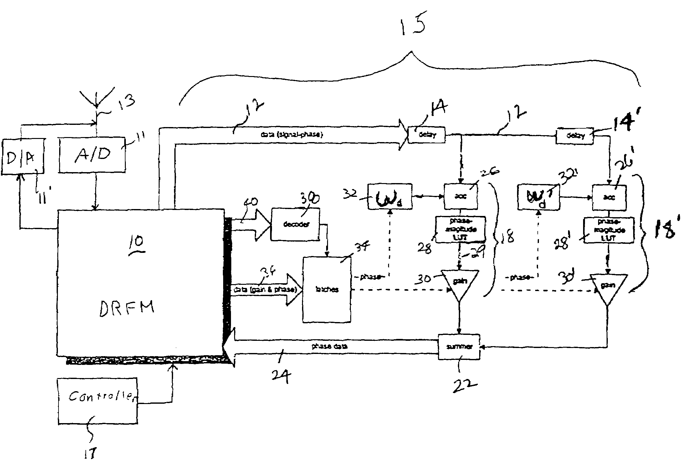
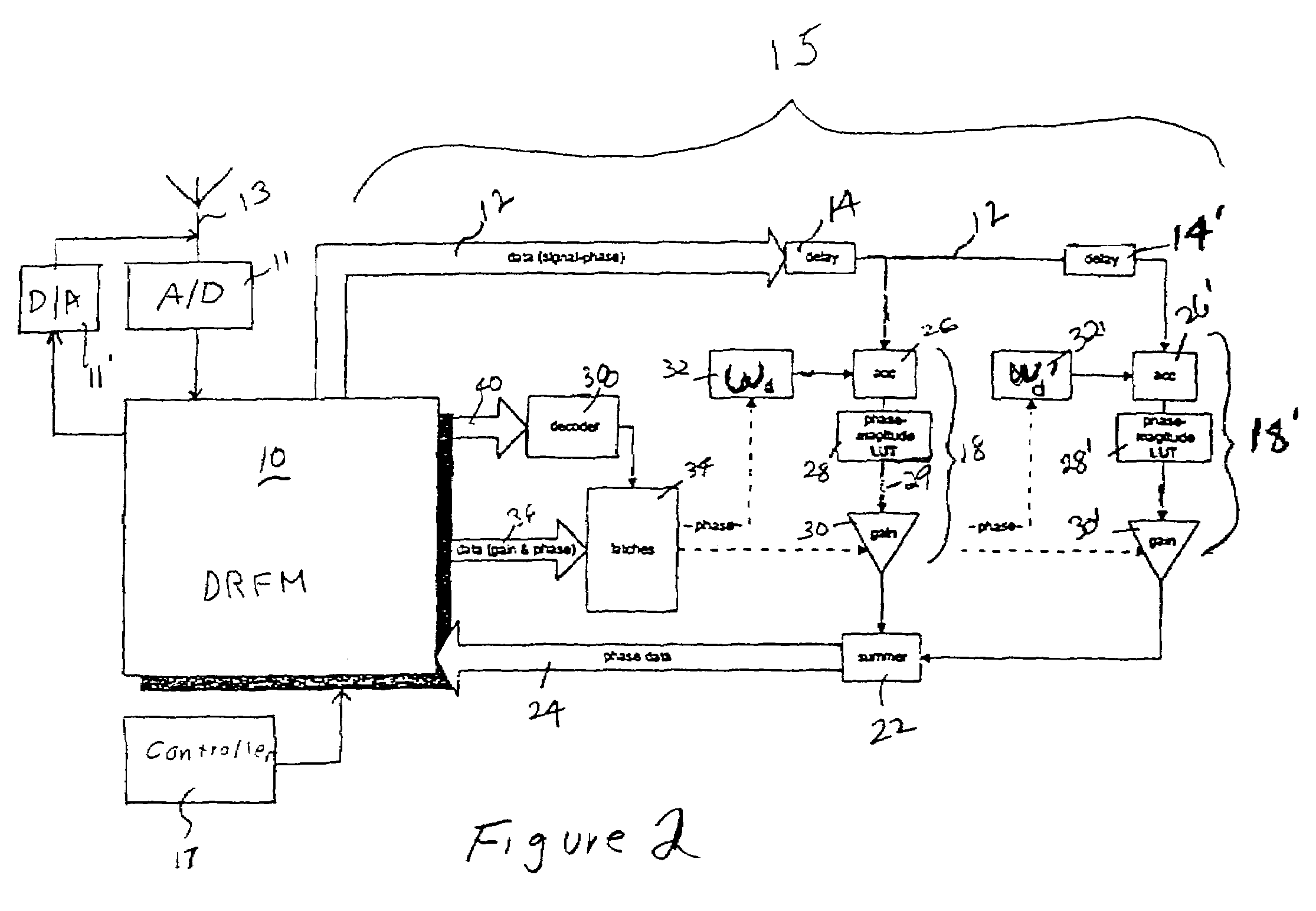
[0015]With reference to the drawing figures, wherein like numbers indicate like parts throughout the several views, FIG. 2 shows an embodiment according to the invention. Member 13 is disposed to receive a signal, which, consistent with the non-limiting example of a radar system given above, is illustrated as an antenna, and which could be a radar pulse from a (possibly hostile) search radar. Analog to digital converter 11 digitizes the analog signal from member 13, producing a stream of digital samples which are stored in digital radio frequency memory (DRFM) 10, preferably in the form of phase samples. By phase sample, it is meant simply a digital representation of phase only. Phase data such as this does permit ultimate reconstruction of the original signal. See, T. T. Vu et al., A GaAs Phase Digitizing and Summing System for Microwave Signal Storage, IEEE JOURNAL OF SOLID STATE CIRCUITS, vol. 24, p. 104 (no. 1, February, 1989). Associated with DRFM 10 is digital circuitry 15 for...


PUM


Abstract

A digital synthesizer includes a digital radio frequency memory (DRFM) for storing phase values and corresponding digital signals. The digital synthesizer includes a digital processing circuit receiving input from the DRFM, the circuit including tapped delay lines and a summer summing the output of the tapped delay lines. The digital synthesizer includes a signal modulator independently synthesizing within each tapped delay line a frequency modulated and gain scaled signal, wherein input to the tapped delay lines are phase values from the DRFM.

Description

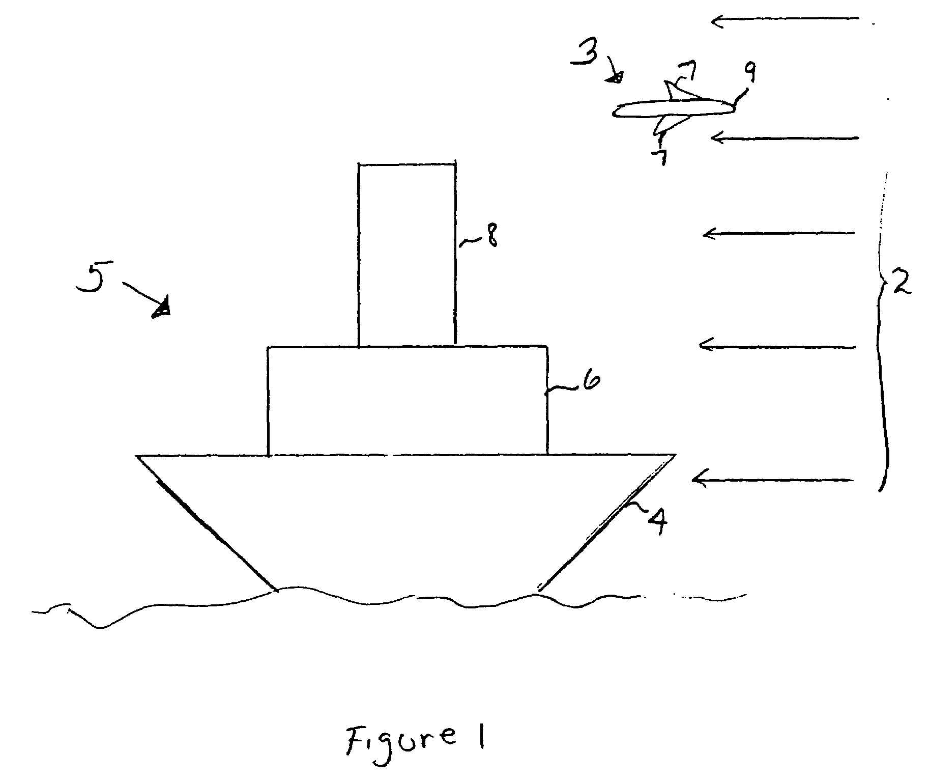
BACKGROUND OF THE INVENTION[0001]Systems which coherently sum a series of tapped delay lines are relevant to a wide range of signal processing applications, transverse filtering being a prominent example. Another example is that of decoy repeaters. An object will modify any signal reflected from it according to the object's shape, and the object's velocity relative to the signal. This permits a hostile interrogator to identify the nature of such objects, which, if the objects are military platforms such as warships or aircraft, is not desirable. One solution has been to artificially synthesize fake characteristic echo signatures in response to receipt of an interrogating signal. Thus, for example, a series of decoy buoys deployed at sea could simulate the presence of a naval flotilla, and thereby potentially disrupt enemy plans.[0002]FIG. 1 illustrates broadly how this is done for a ship 5 and an aircraft 3, in the line of sight of an interrogating signal 2. For illustrative purpose...

Claims


Application Information

Patent Timeline
Patent Type & Authority Patents(United States)
IPC IPC(8): G01S7/38G06F1/02H03B21/00H03H7/30G01S7/40
CPCG01S7/38G01S7/537
Inventor PACE, PHILLIP E.SURRATT, ROBERT E.YEO, SIEW-YAM
Owner THE UNITED STATES OF AMERICA AS REPRESENTED BY THE SECRETARY OF THE NAVY
Learn More