Method and apparatus for electrostatic spray

a technology of electrostatic spray and electrostatic spray, which is applied in the direction of electrostatic spraying apparatus, lighting and heating apparatus, burners, etc., can solve the problems of high electrical energy storage in such a high-voltage reservoir, low charge density, and process instability, and achieve high charging current

Inactive Publication Date: 2006-12-19
BIOMED PROTECT
View PDF31 Cites 54 Cited by
  • Summary
  • Abstract
  • Description
  • Claims
  • Application Information

AI Technical Summary

Benefits of technology

[0013]Generally, according to the process of this invention, an electrode with high voltage is placed at a position near a grounded nozzle made from a conductive material, where the liquid is sprayed by hydraulic pressure or by compressed air. The position of the electrode is chosen to be where the liquid has been atomized to separated particles to avoid electric current leaking through the connected liquid path to the grounded nozzle. The electrode should not be so close to the sprayed particles or the liquid jet that the particles lose charge to the electrode or so far that the electric field becomes too weak in the region between the electrode and the nozzle to induce a high charging current. The shape of the electrode should be similar to the sprayer pattern, e.g. an axisymmetric circular aperture electrode to produce a circular cone spray, or two linear electrodes, one on each side of a flat spray, e.g., a fan spray or a sheet spray, so that electric charges can be induced onto the majority of the liquid particles. In this process, the charge on the sprayed particles has the polarity that is opposite to the voltage, i.e., electrical potential, on the electrode. When spraying a conductive liquid, according to a preferred embodiment of this invention, the electrode is mounted on a non-conducting electrode holder through which an electrically conducting cable connects the electrode to the high voltage power supply, and this electrode holder is surrounded by an electrically insulating concave cup. The open end of the cup is situated away from the direction of the spray so that the insulating cup maintains a dry surface on a portion of the electrode holder so that a significant electric current will not leak from the electrode to a grounded surface via the wetted surfaces and cause a significant drop in the voltage on the electrode. In another embodiment according to this invention, the electrode is positioned close enough so that the particles of the high-pressure jet will collect charges of the same polarity from the electrode and also have sufficient speed so that the charge cannot drain back to the electrode as the particle moves forward with the spray away from the electrode.
[0015]In the preferred embodiments of this invention, the high voltage is generated with an unregulated, low-power, typically less than 5 W, converter that convert a low-voltage, e.g. 0–15 V, DC input into a high-voltage, e.g. 1–20 kV, DC output. The spray gun can be any existing airless gun where the liquid is atomized by the hydraulic pressure or an air gun that uses compressed air to break the liquid into particles, provided that the spray nozzle is electrically conductive and grounded. The electric connection between the nozzle and ground can be achieved with an electric wire or simply through the liquid path, if the liquid's resistivity is not very high. The electrostatic spray gun in this invention is relatively safe because the spray gun and the liquid path are grounded and, when a short circuit occurs, the output voltage of the converter will quickly drop to the same level as the input to avoid electric shock.
[0017]Surrounding the manifold, nozzles, and electrode is a conducting electrode cover, which also has an opening so that the sprayed particles can exit the assembly with minimal interception of particles from the spray by the cover. This conducting electrode cover is to be grounded as are any exterior metal parts of the spray gun so that the build-up of charge or a dangerous electrical potential on any exposed surface of the spray gun assembly is avoided. In this way, the electrode cover acts as an electrical safety shield, and the operator is protected from inadvertent contact with an exposed surface at high voltage. Although the electric field between the conductive electrode cover and the electrode may act to slow the aerosol particles, the change in velocity is small, typically, even for particles with charge that is comparable to the Rayleigh limit.

Problems solved by technology

Although tribo-electric charging is simple, its charge density is low and the process may be unstable.
The electrical energy stored in such a high-voltage reservoir is very high and could cause deadly electric shock if the operator is not carefully isolated, i.e., insulated from the high voltage.
Typically, such insulation comprises an undesirable contribution to the weight and size of the sprayer unit.
Similar to corona, the pre-charge method could add high electric charge into the liquid and aerosol, but the risk of electric shock is also great.
One common problem of all of the above corona and induction electrostatic charging methods is that they require high-speed compressed air to atomize the liquid into fine particles.
Although a high-speed compressed-air flow can both effectively break the liquid into fine particles and also prevent the formation of an electrical conduction leakage path between the electrode and the nozzle, the air flow could significantly reduce the transfer efficiency as many liquid particles may be carried away by the high-speed air flow and be deflected from the target surface.
In some applications, such a high speed air flow is not desirable because the air flow may dislodge particulate or other contamination from the target surface and spoil the purpose for which the sprayed material is applied.
In this case, a high-speed air flow may dislodge and blow contamination, e.g., a chemical or biological agent, from the target surface into the atmosphere or onto an adjacent surface, thus comprising the unwanted spread of the contamination material.
Another major problem of using compressed air or gas is that it requires either a source of compressed gas such as a chemical reaction, or a container of compressed gas such as a compressed air cylinder or tank, or a significant expenditure of power to obtain the high air pressure and flowrate that are sufficient for the atomization and aerosol delivery.
Another major limitation of the prior art is that the implementation usually requires a specially designed spray gun and unique nozzles that are much more expensive than regular non-electrostatic spray guns.
In fact, the additional high capital cost is why electrostatic spraying is applied only in very small percentage of agricultural and industrial applications.
Without electrostatics, a significant portion of the spray is usually wasted, e.g., spray that misses the target is called overspray.
Examples are found in the spraying of pesticides and paint, where overspray not only makes the cost of the application higher, but it also contributes to causing more pollution.
Yet another reason for the limited use of electrostatic spraying is the potential hazard posed by the use of high voltage.
However, this approach results in exposed high voltage components and the possibility of the spray acting as a conduction path that could result in an inadvertent contact of personnel with the high voltage, and so means to exclude personnel from the vicinity of the spray gun and spray are necessary.

Method used


Image

  • Method and apparatus for electrostatic spray
  • Method and apparatus for electrostatic spray
  • Method and apparatus for electrostatic spray

Examples


Embodiment Construction

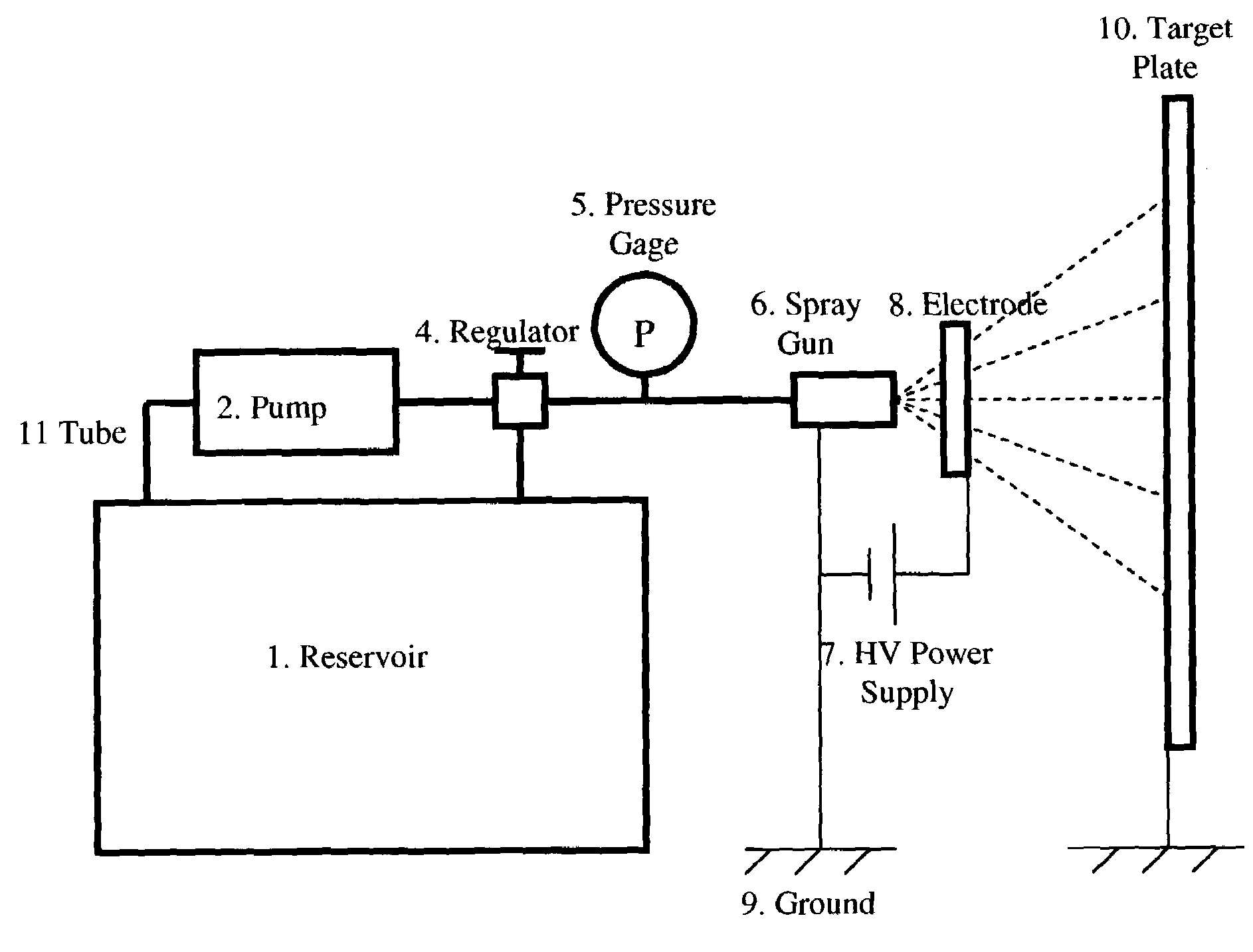
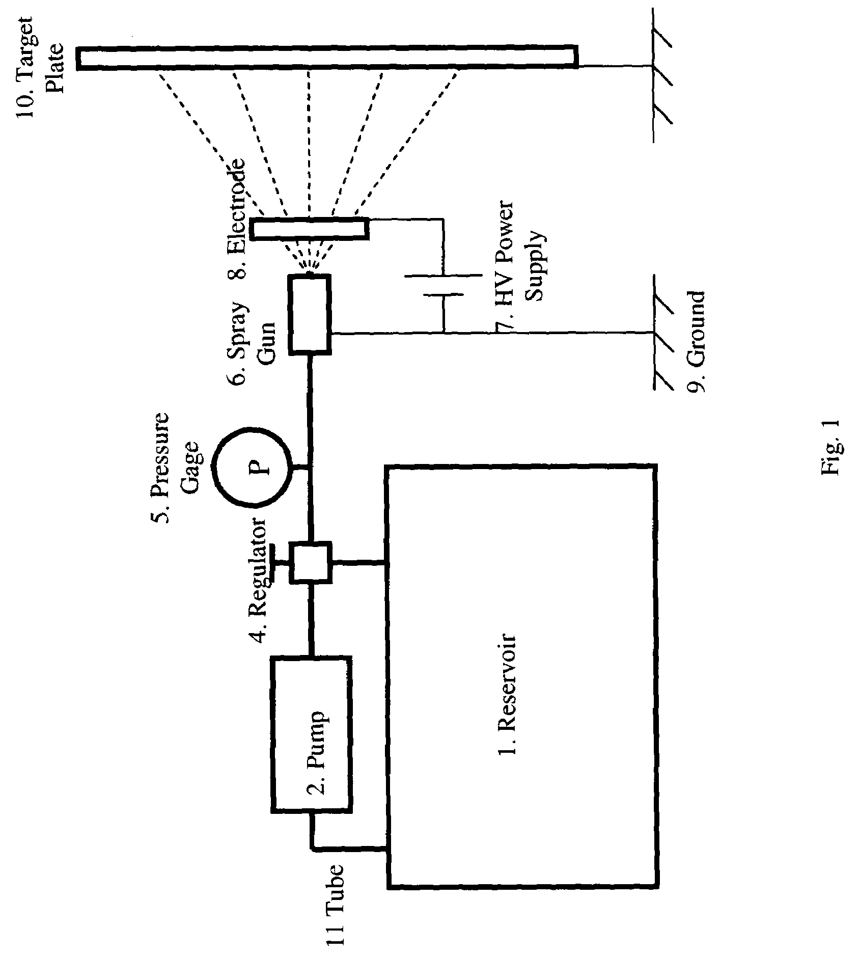
[0035]An apparatus for electrostatic spray in accordance with the principles of the present invention is illustrated schematically in FIG. 1. The liquid or particles to be sprayed are contained in reservoir 1, which is connected by a tube 11 to a pump 4. The spray pressure is controlled by a regulator 4 and displayed by a pressure gage 7. The spray gun 6 is an integration of a valve and nozzle where the liquid or powders separate into particles. The electrostatic charge is induced from the ground 9 through the spray gun onto the particles by the high voltage on the electrode 8. The high voltage is generated by a high-voltage (HV) converter 7 which converts a low voltage DC signal into high-voltage DC output. The particles are sprayed toward a grounded object 10, e.g. a plate, where the charge on the particles is conducted back to ground 9. Instead of airless spray, the liquid or the powder could be atomized by compressed air supplied from an air compressor (not shown) into the spray...


PUM


Abstract

A method and apparatus to improve the atomization of liquid and the efficiency of depositing liquid particles onto target objects, or to coat the target object with a thin film of liquid, to reduce the risk of high-voltage electrical shock, and to reduce the weight of an electrostatic spray system has been developed by inducing electrostatic charges onto the atomized liquid particles sprayed from a grounded metal nozzle.

Description

CROSS-REFERENCE TO RELATED APPLICATIONS[0001]U.S. Provisional Application No. 60 / 401,563 filed Aug. 6, 2002.STATEMENT REGARDING FEDERALLY SPONSORED RESEARCH OR DEVELOPMENT[0002]This work was part of a project supported by the Technical Support Working Group (Contract DAAD05-02-C-0017). The Federal Government retains Unlimited Rights, including the right to use, modify, perform, display, release, or disclose technical data in whole or in part, in any manner or for any purpose whatsoever, and to have or authorize others to do so in the performance of a Government Contract.APPENDIX[0003]Not Applicable.BACKGROUND OF THE INVENTION[0004]1. Field of the Invention[0005]This invention relates to electrostatic-spray methods and apparatus, and in particular to methods of and apparatus for adding electric charges onto liquid to improve the atomization of the liquid and the transfer efficiency, also called the delivery efficiency, of the liquid particles onto target objects.[0006]2. Related Art[...

Claims


Application Information

Patent Timeline
IPC IPC(8): B05B1/08B05B5/00F23D11/32B05B5/025
CPCB05B5/025B05B5/043B05B5/0533
Inventor WANG, SHAUPOHGOLDEN, JEFFRYKOCHER, CHRISTOPHER G.
Owner BIOMED PROTECT
Why Eureka
Try Eureka