
Structures for supporting vibrators

a technology of structure and vibrator, which is applied in the direction of turn-sensitive devices, soldering apparatus, auxiliaries welding devices, etc., can solve the problems of affecting the stability of the gyroscope and substantial temperature drift, and achieve the effect of reducing temperature dri

Inactive Publication Date: 2006-12-12
SEIKO EPSON CORP
View PDF14 Cites 1 Cited by
  • Summary
  • Abstract
  • Description
  • Claims
  • Application Information

AI Technical Summary

Benefits of technology

[0009]An object of the present invention is to provide a novel structure of supporting a vibrator having a terminal for electrical connection so that the vibrator may be miniaturized, and the driving impedance can be made constant in a wide temperature range to reduce the temperature drift.
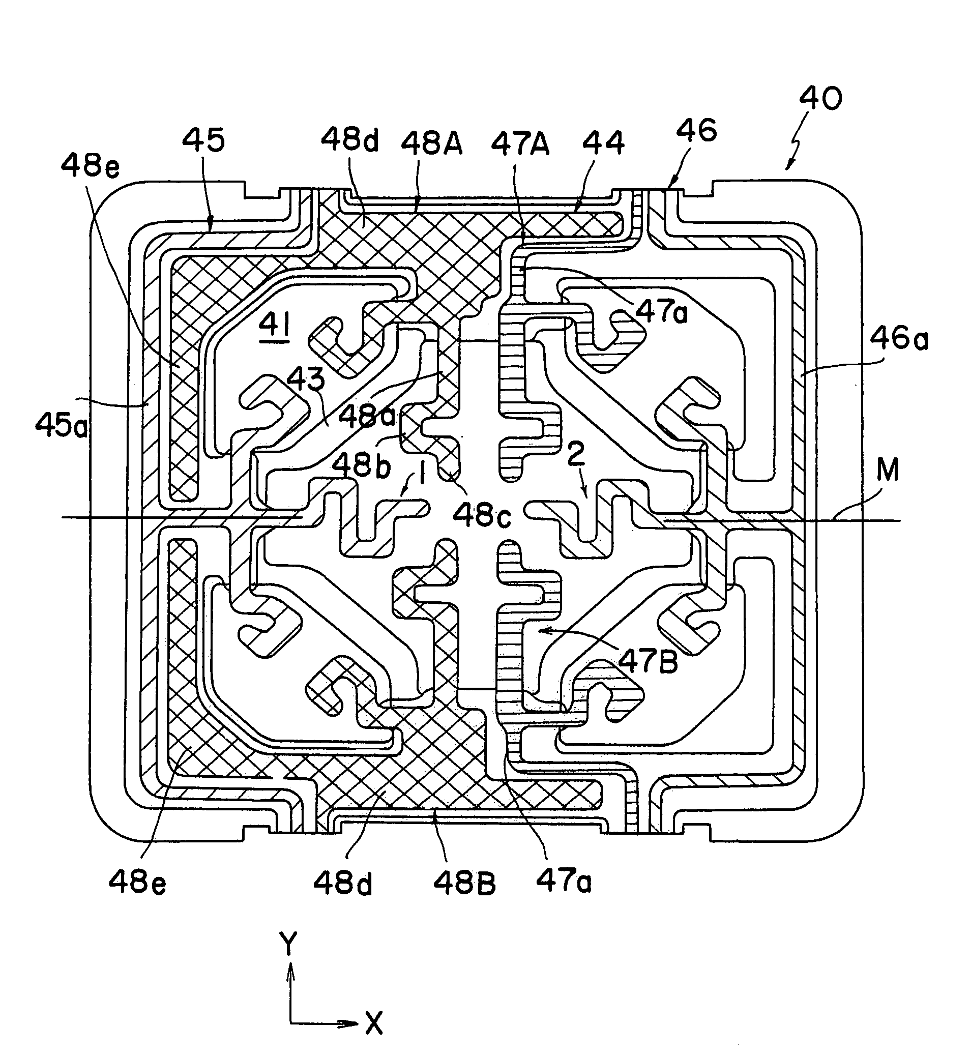
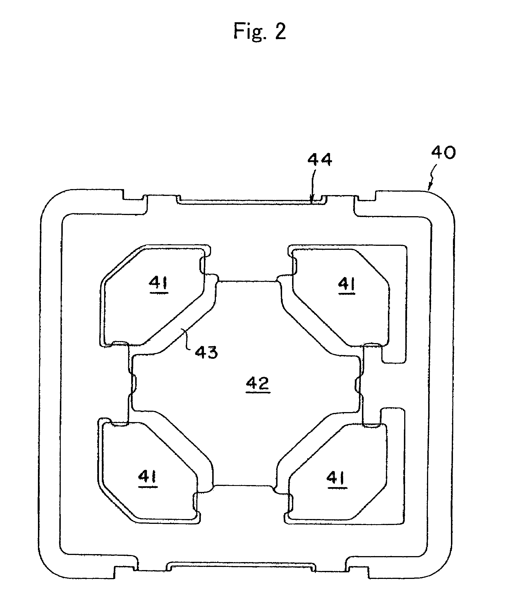
[0011]The inventors have noted a bonding wire for supplying an electrical signal into a terminal of a vibrator or sending a specific electrical signal from the terminal of a vibrator to a packaging substrate. They have thus reached the following idea. That is, a bonding wire is fixed on a substrate and joined with a vibrator so that the vibrator is supported over the surface of the substrate without direct contact with the substrate. A structural strength for supporting a vibrator above the substrate can be assured by means of the bonding wire by miniaturizing the vibrator.

Problems solved by technology

Particularly, when a vibrator is made of a piezoelectric single crystal, the temperature dependency of the single crystal may affect the stability of the gyroscope.
According to such supporting method, however, a substantial temperature drift may be observed, for example, in a high temperature region.

Method used


Image

  • Structures for supporting vibrators
  • Structures for supporting vibrators
  • Structures for supporting vibrators

Examples


examples

[0056]A vibrator shown in FIG. 6 was produced and mounted on the supporting structure shown in FIGS. 1 to 5. A chromium mm of 100 angstroms in thickness and a gold film of 1500 angstroms in thickness were formed in predetermined regions on a wafer made of a Z-plate of quartz with a thickness of 0.1 mm, by sputtering. Both main faces of the wafer were coated with resist films.

[0057]The wafer was then immersed in aqueous solution of iodine and potassium iodide to remove excessive gold in the gold film by etching, and was further immersed in aqueous solution of cerium-ammonium nitrate and perchloric acid to remove excessive chromium in the chromium film by etching. The wafer was etched by immersing the wafer in ammonium bifluoride at a temperature of 80° C. for 20 hours to form the external shape of the vibrator. A gold film having a thickness of 2000 angstrom is formed as a film for electrode on the chromium film having a thickness of 100 angstrom using a metal mask. The vibrator 1 ha...


PUM

PropertyMeasurementUnit
temperatureaaaaaaaaaa
tan δaaaaaaaaaa

Abstract

An object of the present invention is to provide a novel structure of supporting a vibrator having a terminal for electrical connection so that the vibrator can be miniaturized, and the driving impedance can be made constant in a wide temperature range to reduce the temperature drift. The structure has a substrate and bonding wires 45, 46 supported on the surface of the substrate and to be connected with the vibrator. The vibrator is supported with the bonding wire so that the vibrator is not directly contacted with the substrate. The bonding wire is electrically connected with the terminal. The resonance frequency “fr” of the supporting structure, the driving frequency “fd” for the vibrator and the detuning “Δf” satisfy the following formula1.1·Δf≦fr≦0.9·fd.

Description

[0001]This application claims the benefit of a Japanese Patent Application P2003-132920 filed on May 12, 2003, the entirety of which is incorporated by reference.BACKGROUND OF THE INVENTION[0002]1. Field of the Invention[0003]The present invention provides a structure for supporting a vibrator.[0004]2. Related Art Statement[0005]It has been studied to use a vibratory gyroscope as a turning angular rate sensor employed in a vehicle control system of an automobile based on a vehicle turning rate feedback system. Such a system detects the direction of a steering wheel itself by a turning angle of the steering wheel. Simultaneously, the turning rate of the vehicle is detected by the vibratory gyroscope, The system finds a difference by comparing the direction of the steering wheel with the actual vehicle turning velocity, and attains a stable vehicle control by correcting a wheel torque and a steering angle on the basis of this difference.[0006]In a vehicle control system, a vibratory g...

Claims


Application Information

Patent Timeline
Patent Type & Authority Patents(United States)
IPC IPC(8): H01L41/08B23K20/00G01C19/56
CPCB23K20/004G01C19/56H01L24/85H01L24/45H01L2224/45124H01L2224/45147H01L2224/45155H01L2224/4554H01L2224/45644H01L2224/48H01L2224/85H01L2924/01003H01L2924/01006H01L2924/01012H01L2924/01013H01L2924/01028H01L2924/01029H01L2924/01033H01L2924/01039H01L2924/01058H01L2924/01078H01L2924/01079H01L2924/01082H01L2924/04953H01L2924/09701H01L2924/3011H01L2924/00014H01L2924/01019H01L2924/01024H01L2924/01087H01L2924/014H01L24/48H01L2224/85205H01L2924/00
Inventor ISHIKAWA, SEIJITANI, MAKOTOHAYASHI, SHIGEKI
Owner SEIKO EPSON CORP
Learn More