
Planographic printing plate material and planographic printing plate preparing process

a technology material, applied in the field of planographic printing plate, can solve the problems of unsatisfactory preheating latitude considering printing durability, insufficient practical properties, development failure, etc., and achieve the effects of accelerating development, high density image, and easy to increase the accuracy of an optical system

Inactive Publication Date: 2006-11-21
KONICA MINOLTA MEDICAL & GRAPHICS INC
View PDF10 Cites 2 Cited by
  • Summary
  • Abstract
  • Description
  • Claims
  • Application Information

AI Technical Summary

Benefits of technology

[0175]As the laser, argon laser, He-Ne gas laser, YAG laser or semi-conductor laser is preferably used. In the invention, a semiconductor laser employing InGaN type material or ZnSn type material, which can continuously emit light with a wavelength of from 380 to 430 nm, is especially preferred in view of obtaining the effects of the invention.
[0176]As a laser scanning method by means of a laser beam, there are a method of scanning on an outer surface of a cylinder, a method of scanning on an inner surface of a cylinder and a method of scanning on a plane. In the method of scanning on an outer surface of a cylinder, laser beam exposure is conducted while a drum around which a recording material is wound is rotated, in which main scanning is represented by the rotation of the drum, while sub-scanning is represented by the movement of the laser beam. In the method of scanning on an inner surface of a cylinder, a recording material is fixed on the inner surface of a drum, a laser beam is emitted from the inside, and main scanning is carried out in the circumferential direction by rotating a part of or an entire part of an optical system, while sub-scanning is carried out in the axial direction by moving straight a part of or an entire part of the optical system in parallel with a shaft of the drum. In the method of scanning on a plane, main scanning by means of a laser beam is carried out through a combination of a polygon mirror, a galvano mirror and an Fθ lens, and sub-scanning is carried out by moving a recording medium. The method of scanning on an outer surface of a cylinder and the method of scanning on an inner surface of a cylinder are suitable for high density image recording, since it is easier to increase accuracy of an optical system.(Development)
[0177]In the invention, the imagewise exposed light sensitive layer, which are cured are at exposed portions, is developed with an alkali developer, whereby the light sensitive layer at exposed portions are removed to form an image. As the alkali developer, a conventional alkali aqueous solution is used. For example, there is an alkali developer containing an inorganic alkali agent such as sodium silicate, potassium silicate, ammonium silicate, sodium secondary phosphate, potassium secondary phosphate, ammonium secondary phosphate; sodium hydrogen carbonate, potassium hydrogen carbonate, ammonium hydrogen carbonate; sodium carbonate, potassium carbonate, ammonium carbonate; sodium borate, potassium borate, lithium borate; sodium hydroxide, potassium hydroxide, and ammonium hydroxide.
[0178]The alkali developer can contain organic alkali agents such as monomethylamine, dimethylamine, trimethylamine, monoethylamine, diethylamine, triethylamine, monoisopropylamine, diisopropylamine, triisopropylamine, n-butylamine, monoethanolamine, diethanolamine, triethanolamine, monoisopropanolamine, diisopropanolamine, ethyleneimine, ethylenediamine, and pyridine.
[0179]These alkali agents can be used singly or as a mixture of two or more thereof. The alkali developer can contain an anionic surfactant, an amphoteric surfactant, or an organic solvent such as alcohol.
[0180]The developer used in the invention has preferably an aqueous alkali solution having a pH of more than 8.5 to less than 13.0, and more preferably 10.0 to 12.5. The developer has an electric conductivity of preferably from 3 to 30 mS / cm. Electric conductivity lower than the foregoing range usually renders difficult dissolution of the light sensitive layer provided on the surface of an aluminum plate support, leading to stained printing. While an electric conductivity exceeding the foregoing range results in an increased salt concentration, retarding dissolution of the light sensitive layer, resulting in residual layer at unexposed areas. The electric conductivity is more preferably from 5 to 20 mS / cm.

Problems solved by technology

A composition disclosed in this patent document provides excellent sensitivity and printing durability, which is preferred, however, a planographic printing plate material comprising the composition is greatly lowered in storage stability after long term storage, resulting in insufficient practical properties.
However, when printing plate materials having a different thickness were processed, the printing plate materials are heated at preheating to different temperature due to the different thickness, producing problem of causing development failure.
However, satisfactory preheating latitude has not yet obtained considering printing durability.
Further, the above negative-working photopolymerization type printing plate material has problem in that sludge is likely to be produced in a developer, and does not have a satisfactory running property.

Method used


Image

  • Planographic printing plate material and planographic printing plate preparing process
  • Planographic printing plate material and planographic printing plate preparing process
  • Planographic printing plate material and planographic printing plate preparing process

Examples


example 1

[0184]Methyl methacrylate of 58.0 parts (0.58 mol), 35.0 parts (0.41 mol) of methacrylic acid, 6.0 parts (0.05 mol), of ethyl methacrylate, 100 parts of ethanol, and 1.23 parts of α,α′-azobisisobutyronitrile were put in a three neck flask under nitrogen atmosphere, and reacted under nitrogen atmosphere for 6 hours at 80° C. in an oil bath. After that, the reaction mixture was added with 1 part of triethylbenzylammonium chloride and 28.0 parts (0.2 mol) of glycidyl methacrylate (epoxy-containing unsaturated compound) and reacted at 25° C. for additional 3 hours. Thus, polymer binder A was obtained. The weight average molecular weight of the polymer binder A was 70,000, measured according to GPC.

[0185]Polymer binders B and C were prepared in the same manner as in Polymer binder A, except that a mixture ratio pf monomers, and an addition amount of the epoxy compound for reacting with the carboxyl group were changed as shown in Table 1, and polymerization time was adjusted to give a wei...

example 2

[0204]Planographic printing plate material samples No. 12 through 28 were prepared in the same manner as in Example 1, except that the polymer binder, the co-initiator and the dye were changed to those as shown in Table 3, and evaluated in the same manner as in Example 1. Herein, the following printing durability 2 was further evaluated.

>

[0205]Printing was carried out except that soybean ink Naturalith 100 produced by Dainippon Ink Kagaku Kogyo Co., Ltd. was used as printing ink. The number of prints printed from the beginning of the printing till when dots at highlight image portions were reduced by 3% or filling-up was observed at shadow portions was evaluated as a measure of printing durability 2.

[0206]The results are shown in Table 3.

[0207]

TABLE 3PrintingPrintingStorage StabilityDura-Dura-PrintingCo-Sensi-bility 1bility 2DurabilityPreheat-SludgeSamplePolymeriniti-Dye 3tivity(x(xSensi-1 (xingAmountNo.Binderator(R)(μj / cm2)10,000)10,000)tivity10,000)Latitude(g)12BCI-13Octyl7077No71...


PUM

PropertyMeasurementUnit
emission wavelengthaaaaaaaaaa
temperatureaaaaaaaaaa
mol %aaaaaaaaaa

Abstract

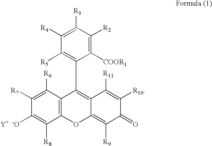
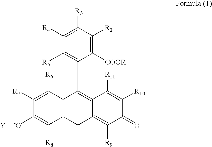
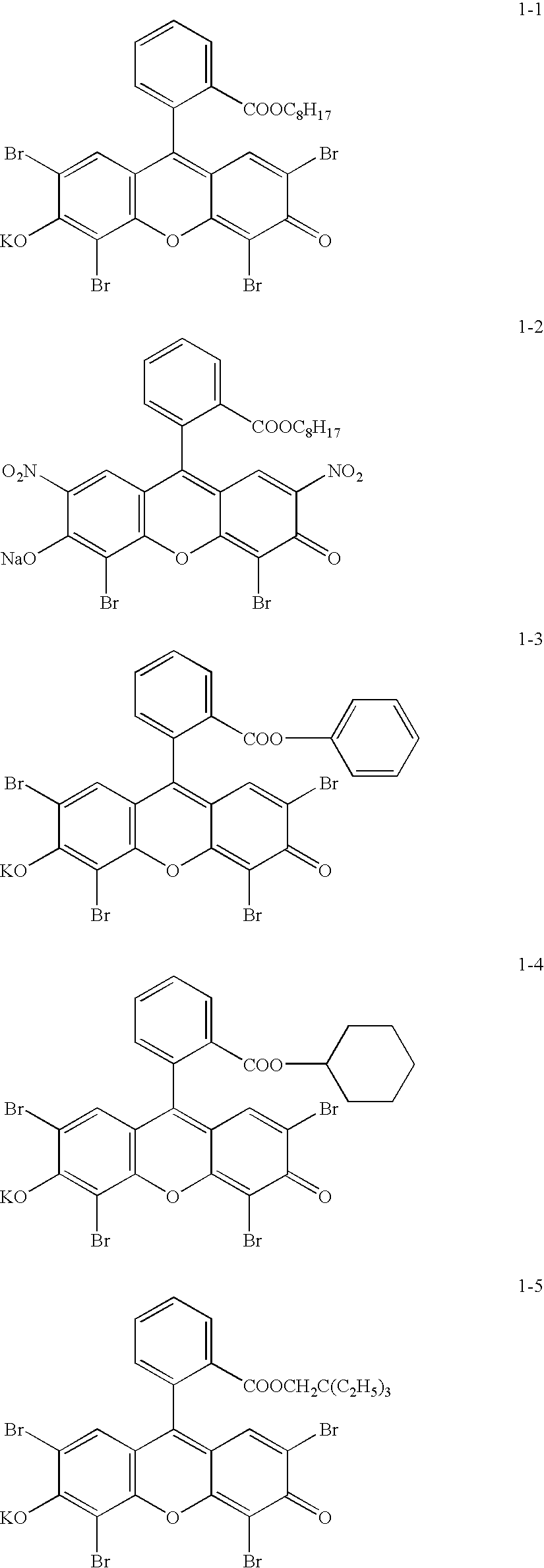
Disclosed is a planographic printing plate material comprising a hydrophilic support and provided thereon, a light sensitive layer and an overcoat layer in that order, wherein the light sensitive layer contains (a) an alkali soluble polymer, (b) a polymerizable compound having an ethylenically unsaturated bond, (c) a polymerization initiator, and (d) an anionic dye represented by the following formula (1),

Description

FIELD OF THE INVENTION[0001]The present invention relates to a planographic printing plate material with high sensitivity which is capable of being exposed with laser, and a process of preparing a planographic printing plate employing the same, and particularly to a planographic printing plate material capable of being exposed with low power laser, which improves storage stability and preheating latitude, and minimizes sludge, and a process of preparing a planographic printing plate employing the same.BACKGROUND OF THE INVENTION[0002]In recent years, as a printing plate for off-set printing, a large number of computer to plate (CTP) systems have been developed and put into practical use, which imagewise exposes directly to a planographic printing plate material employing laser light based on digital image data to record an image on the material. As the CTP systems, there are a silver salt system, a radical polymerization system and a thermal system, which differ in characteristics.[...

Claims


Application Information

Patent Timeline
Patent Type & Authority Patents(United States)
IPC IPC(8): G03F7/029G03F7/004G03F7/00G03F7/027G03F7/031G03F7/033G03F7/11
CPCG03F7/029G03F7/031
Inventor KUROKI, TAKAAKI
Owner KONICA MINOLTA MEDICAL & GRAPHICS INC
Learn More