
Complex composite structures and method and apparatus for fabricating same from continuous fibers

a composite structure and continuous fiber technology, applied in the field of composite structures, can solve the problems of unexpected stiffness of structures, strength or load bearing capacity per unit weight, and difficulty in fabrication of such structures, and achieve the effect of achieving wide-spread application of such structures and avoiding the failure of structural rigidity and strength

Inactive Publication Date: 2006-11-07
ISOTRUSS IND LLC
View PDF52 Cites 39 Cited by
  • Summary
  • Abstract
  • Description
  • Claims
  • Application Information

AI Technical Summary

Benefits of technology

[0013]It has been recognized that it would be advantageous to develop an apparatus and / or method for fabricating complex structures, such as those with complex helical configurations. In addition, it has been recognized that it would be advantageous to develop such structures to prevent or resist the formation of gaps between overlapping fibers.
[0017]In accordance with another more detailed aspect of the present invention, the method can further include arranging a plurality of continuous fibers to form a plurality of elongated strands in a predetermined orientation including at least two different strands with different orientations that intersect one another at the nodes. The plurality of fibers can be overlapped and consolidated at the nodes. The fibers can be compacted at the nodes to reduce gaps. The fibers can be consolidated by twisting the strands. In addition, the fibers can be consolidated by wrapping other fibers around the strands to form a core of substantially unidirectional fibers wrapped with a layer of outer fibers. In addition, the strands can be consolidated by braiding at least one of the strands. Furthermore, the strands can be consolidated by braiding other fibers around the strands to form a core of substantially unidirectional fibers wrapped with a layer of outer braided fibers.

Problems solved by technology

As stated above, such structures have shown unexpected stiffness, and strength or load bearing capacity per unit weight.
The fabrication of such structures, however, has proven to be very difficult.
Wide-spread application of such structures has been frustrated by the inability to quickly, easily, and / or inexpensively manufacture such structure.
It also will be appreciated that such complex geometries have proven ill suited for conventional manufacturing techniques.
None of these existing technologies appears suited for continuous or volume manufacturing of such complex, three-dimensional structures described above.
For example, it will be appreciated that the complex, three-dimensional nature of the structure, with the straight segments extending through the structure between external nodes, makes any mandrel shaped as the structure difficult to remove from the structure itself.
Similarly, it will be appreciated that the complex, three-dimensional structure has a varying cross-sectional shape, and discontinuous or open surface structure, which is ill-suited for conventional pultrusion techniques.
In addition, the intersections of the various helical components at the nodes have also proven problematic.

Method used


Image

  • Complex composite structures and method and apparatus for fabricating same from continuous fibers
  • Complex composite structures and method and apparatus for fabricating same from continuous fibers
  • Complex composite structures and method and apparatus for fabricating same from continuous fibers

Examples


Embodiment Construction

[0061]Reference will now be made to the exemplary embodiments illustrated in the drawings, and specific language will be used herein to describe the same. It will nevertheless be understood that no limitation of the scope of the invention is thereby intended. Alterations and further modifications of the inventive features illustrated herein, and additional applications of the principles of the inventions as illustrated herein, which would occur to one skilled in the relevant art and having possession of this disclosure, are to be considered within the scope of the invention.

[0062]The present invention introduces a unique methodology referred to as tensioned fiber placement or casting, which has demonstrated surprising utility for fabricating or casting complex, composite fiber / resin structures in free-space. The method involves interlacing one or more rotating strands of transverse fibers with an array of tensioned, longitudinal fibers to form a support skeleton suitable for further...


PUM

PropertyMeasurementUnit
structureaaaaaaaaaa
forceaaaaaaaaaa
load bearing capacityaaaaaaaaaa

Abstract

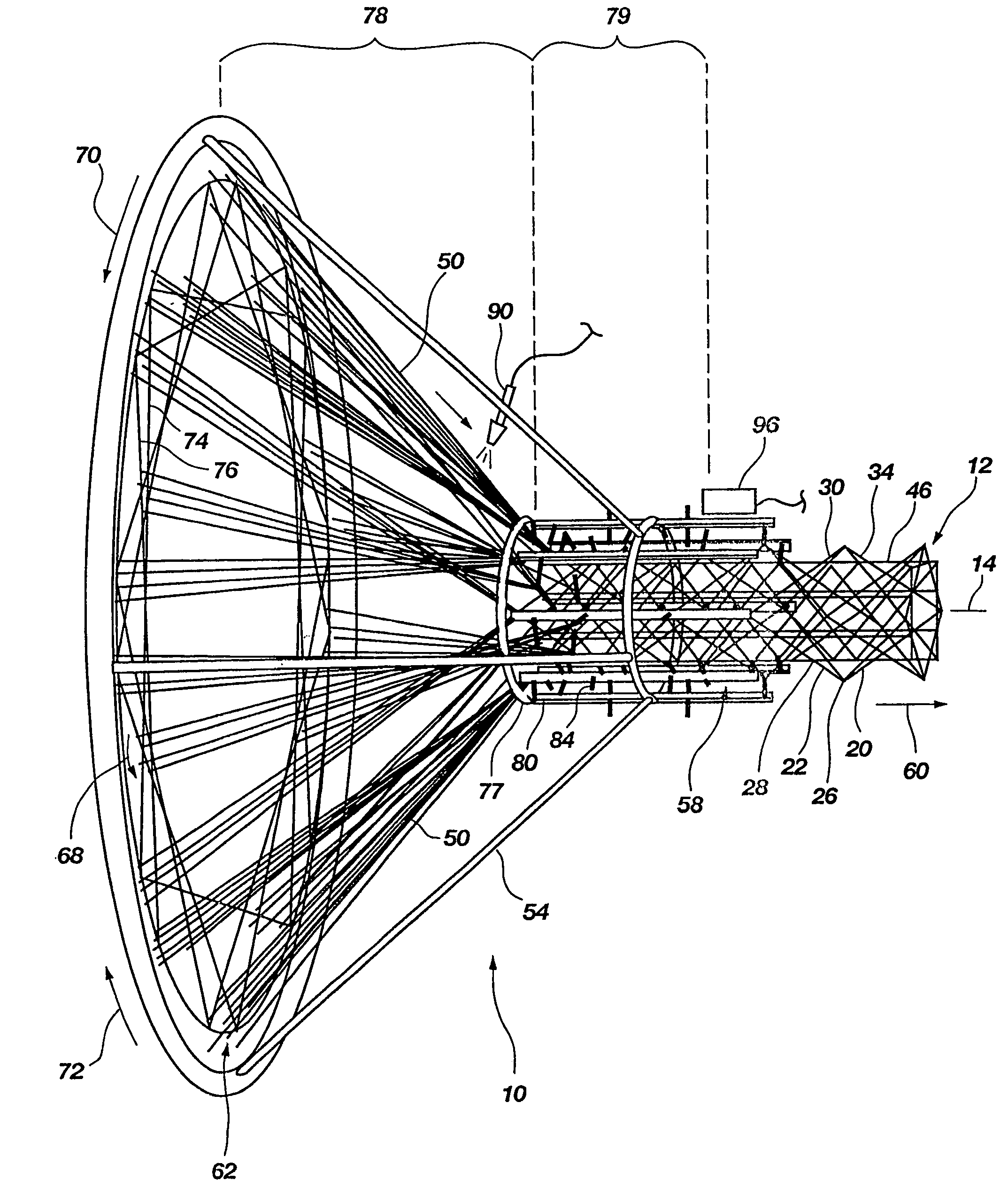
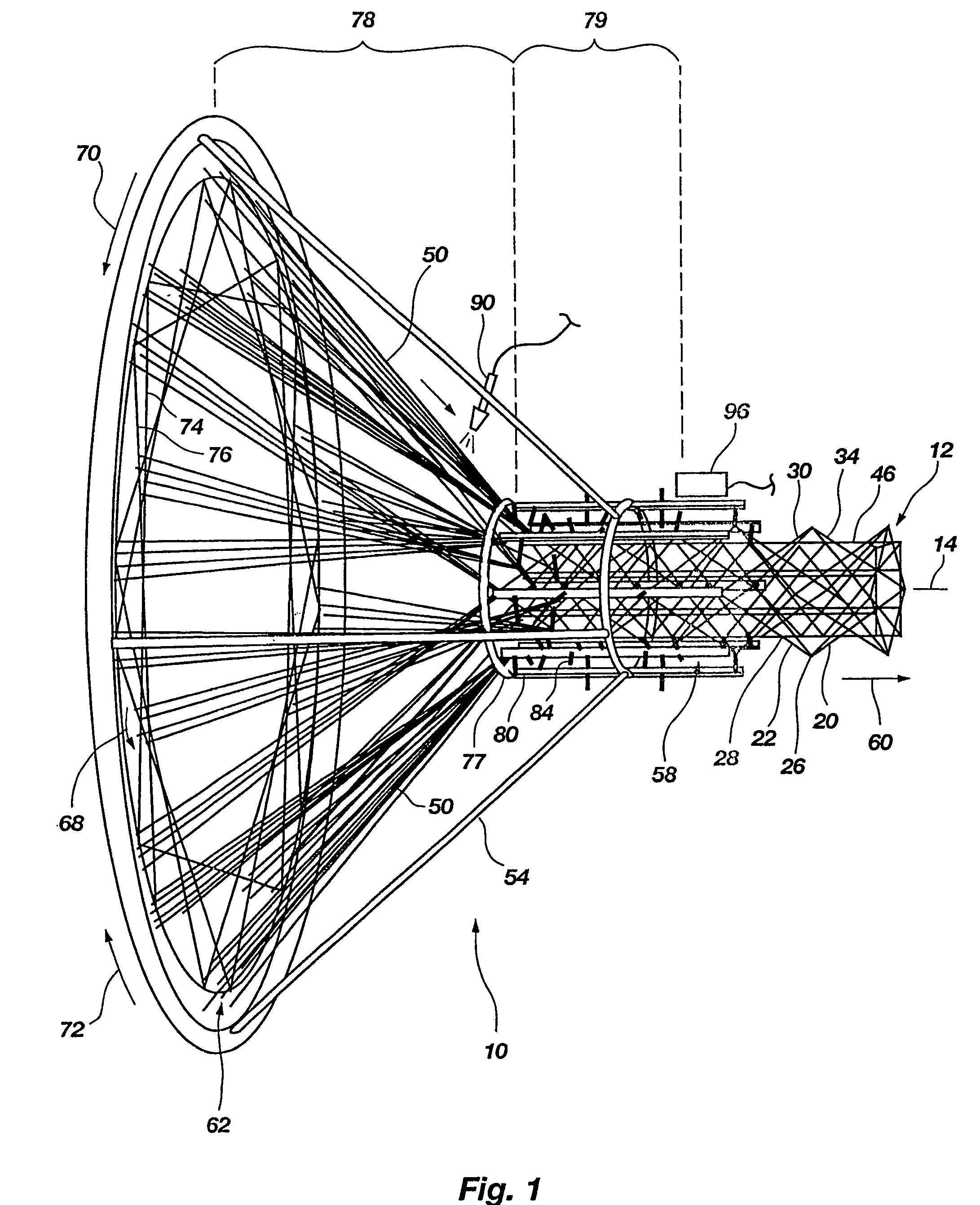
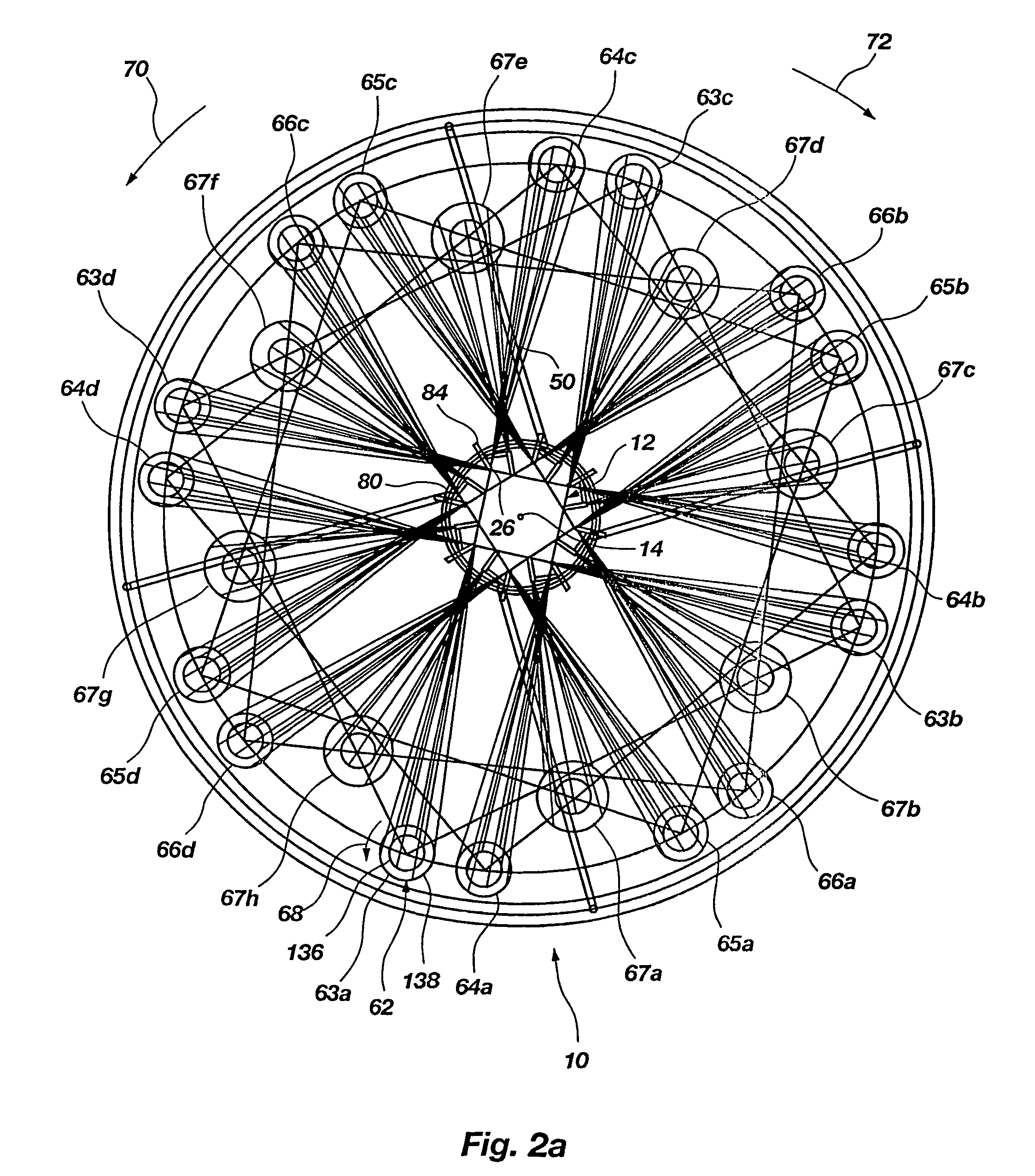
A method and apparatus for fabricating a complex, three-dimensional structure (12), such as a truss, from composite fiber / resin includes pulling a plurality of continuous fibers (50) from a feed source (62) along a processing path (58) about a longitudinal axis (14). At least some of the fibers are wound around the longitudinal axis in opposite directions (70,72) by rotational elements to form helical and reverse helical components (30, 34) that intersect at nodes (26,28). Select nodes are engaged by engagement members (84) and are maintained radially outwardly from the longitudinal axis by a support frame (80) to create sequential discrete segments (22) in the helical and reverse helical components. The select nodes can be engaged and maintained from outside the helical and reverse helical components. Resin can be applied to the fibers by resin applicator (90) and cured. A three-dimensional structure (200) can be formed with one or more continuous fibers forming two or more different components (204, 206) of the structure and transitioning at transition nodes (207). A three-dimensional structure can be formed with the components including a sleeve (162) of braided fibers surrounding a core (163) of elongated fibers to reduce gaps.

Description

[0001]This application claims the benefit of U.S. provisional patent application No. 60 / 313,291 filed Aug. 17, 2001.BACKGROUND OF THE INVENTION[0002]1. Field of the Invention[0003]The present invention relates generally to complex, composite structures and an apparatus and method for fabricating such complex structures from composite fiber / resin. More particularly, the present invention relates to an apparatus and method for fabricating complex structures with a plurality of helical and / or reverse helical components, such as trusses or cylinders.[0004]2. Related Art[0005]Complex truss structures have been described in U.S. Pat. No. 5,921,048 that can have enhanced load bearing capacity per unit weight. Such structures can have complex configurations, including for example, a plurality of helical components formed around a longitudinal axis in opposite directions. Each helical component can include a plurality of sequential straight segments coupled end-to-end in a helical configurat...

Claims


Application Information

Patent Timeline
Patent Type & Authority Patents(United States)
IPC IPC(8): B65H81/00B29C53/56B29C53/80B29C70/22D04C1/06D04C3/00D04C3/40E04C3/28E04C3/29E04C3/46
CPCB29C53/564B29C53/8016B29C70/222D04C1/06E04C3/28E04C3/291E04C3/46D04C3/48D04C3/40B29C53/8066Y10T428/2913D10B2505/02D10B2403/02411E04H12/00
Inventor JENSEN, DAVID W.
Owner ISOTRUSS IND LLC
Learn More